Operation, Testing & maintenance, Wiring the a.c. input – IOTA ISL-28 User Manual
Page 3: Labels, Completing installation
Page 3
6. WIRING THE A.C. INPUT
A. The
ISL-28 and A.C. ballast must be on the same branch circuit.
B. The
ISL-28 requires an unswitched A.C. power source of either 120 or 277 volts. Select the proper voltage
lead and cap the unused lead.
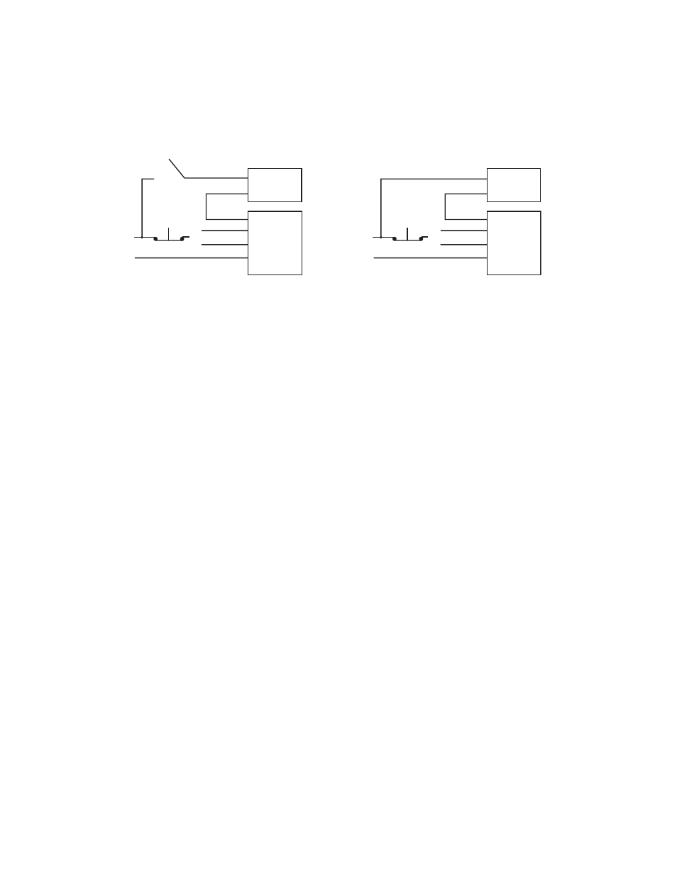
C. When the
ISL-28 is used with a switched fixture, the A.C. input to the ISL-28 must be connected ahead of the
fixture switch. Refer to Illustration 2 for switched and unswitched fixture wiring diagrams.
7. LABELS
Attach the appropriate labels adjacent to the
Test Switch and Charge Indicator. Annotate Re-lamping label for
lamp type and wattage. The Caution and the Re-lamping labels must be on the fixture in a readily visible location
to anyone attempting to service the fixture.
8. COMPLETING INSTALLATION
When the installation is complete, switch the A.C. power on and join the
ISL-28 unit connector.
OPERATION
Normal Mode – A.C. power is present. The A.C. ballast operates the fluorescent lamp(s) as intended. The ISL-28 is in the
standby charging mode. The
Charge Indicator will be lit providing a visual indication that the battery is being charged.
Emergency Mode – The A.C. power fails. The ISL-28 senses the A.C. power failure and automatically switches to the
Emergency Mode. One lamp is illuminated, at reduced output, for a minimum of 90 minutes. When the A.C. power is
restored, the
ISL-28 switches the system back to the Normal Mode and resumes battery charging. See page 1 of the
Instruction Manual.
TESTING & MAINTENANCE
Pressing the
Test Switch turns off the light on the Charge Indicator and forces the unit into emergency mode, inter-
rupting power to the designated A.C. ballast. The emergency lamp is now being lit by the
ISL-28 unit. After releasing
the
Test Switch, the fixture returns to normal operation after a momentary delay. To simulate a “BLACK OUT” use the
circuit breaker to turn off A.C. power.
Initial Testing – Allow the unit to charge approximately 1 hour, then conduct a short discharge test. Allow a 24 hour
charge before conducting a one hour test.
The
ISL-28 is a maintenance free unit, however, periodic inspection and testing is required. NFPA 101, Life Safety
Code, outlines the following schedule:
Monthly – Insure that the Charge Indicator light is illuminated. Conduct a 30 second discharge test by depressing the
Test Switch. One lamp should operate at reduced output.
Annually – Insure that the Charge Indicator light is illuminated. Conduct a full 1
1
/
2
hour discharge test. The unit should
operate as intended for the duration of the test.
“Written records of testing shall be kept by the owner for inspection by the authority having jurisdiction.”
SERVICING SHOULD BE PERFORMED BY QUALIFIED PERSONNEL.
Consult Customer Service or visit www.iotaengineering.com for current warranty information.
BLACK
A.C. BALLAST
HOT A.C. LINE
WHT
WHITE
(120V) BLK
(277V) ORG
TEST SWITCH
COMMON
Select proper voltage lead. Cap unused lead.
WHT/BLK
BLACK
A.C. BALLAST
HOT A.C. LINE
WHT
WHITE
(120V) BLK
(277V) ORG
TEST SWITCH
COMMON
Select proper voltage lead. Cap unused lead.
WHT/BLK
WALL SWITCH
➀
➀
➀
➀
Illustration 2 Switched Fixture
Unswitched Fixture
ISL-28
ISL-28