Appendix pinout assignments – Hatteland Display 26 inch - HD 26T21 STD (Widescreen) User Manual
Page 98
98
IND100241-13
Appendix
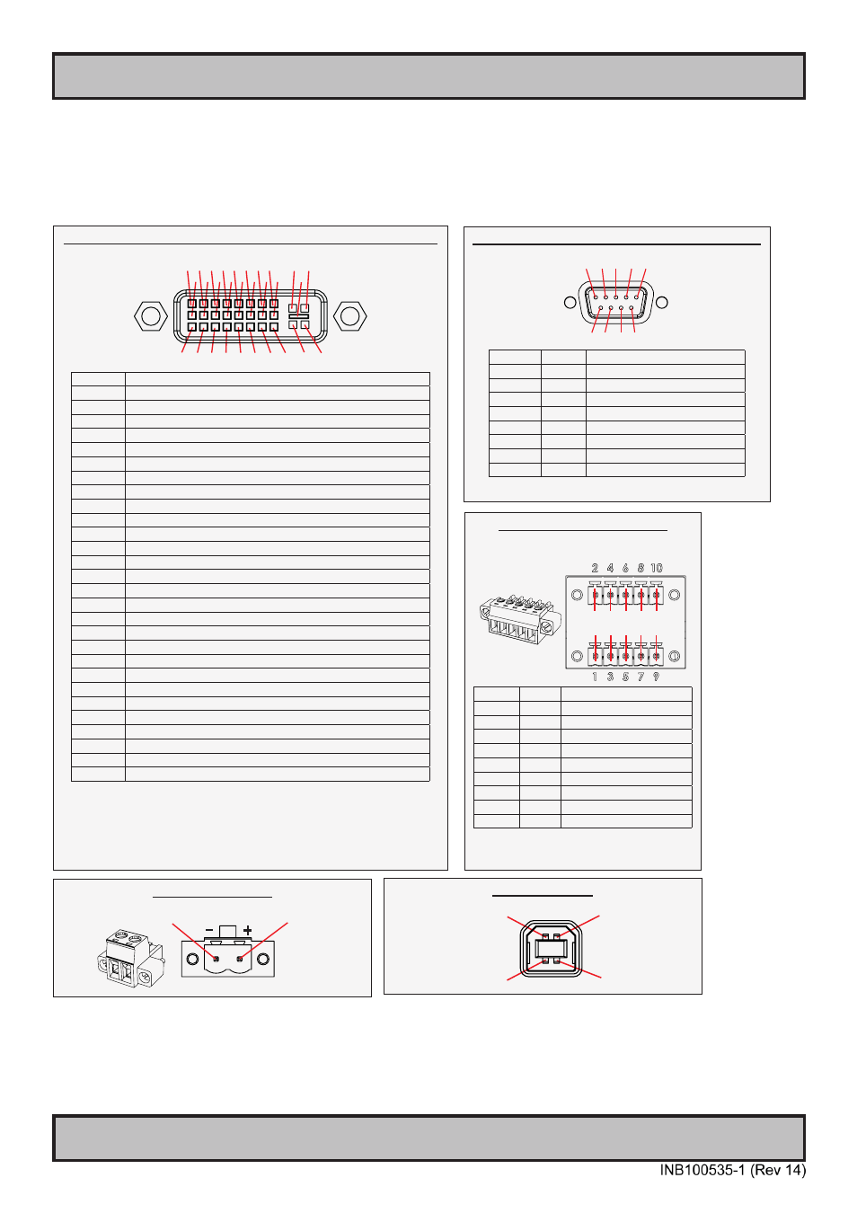
Pinout Assignments
Connectors illustrated here are either standard by factory default or may be available (through factory customization).
Note that some combinations may not be possible due to space restrictions. List also valid for customized models. All
pin out assignments are seen from users Point of View (POV) while looking straight at the connector. Please review
the dedicated datasheet or technical drawings for your actual unit to identify and determine the presence of desired
connector. Detailed information about Housing Connectors (terminal blocks) can be found earlier in this manual.
18/24/24+5 pin DVI-D, DVI-I, Single Link, Dual Link Combined Female
1 2 3 4 5 6 7 8 C1 C2
9 10 11 12 13 14 15 16 C5
17 18 19 20 21 22 23 24 C3 C4
PIN 01 T.M.D.S. Data2 - (Digital - RED link 1)
PIN 02 T.M.D.S. Data2 + (Digital + RED link 1)
PIN 03 T.M.D.S. Data2/4 Shield
PIN 04 T.M.D.S. Data4 - (Digital - GREEN link 2)
PIN 05 T.M.D.S. Data4 + (Digital + GREEN link 2)
PIN 06 DDC Clock
PIN 07 DDC Data
PIN 08 Analog Vertical Sync (DVI-I only)
PIN 09 T.M.D.S. Data1 - (Digital - GREEN link 1)
PIN 10 T.M.D.S. Data1 + (Digital + GREEN link 1)
PIN 11 T.M.D.S. Data1/3 Shield
PIN 12 T.M.D.S. Data3 - (Digital - BLUE link 2)
PIN 13 T.M.D.S. Data3 + (Digital + BLUE link 2)
PIN 14 +5V Power (for standby mode)
PIN 15 Ground (for +5V and analog sync)
PIN 16 Hot Plug Detect
PIN 17 T.M.D.S. Data0 - (Digital - BLUE link 1) and digital sync.
PIN 18 T.M.D.S. Data0 + (Digital + BLUE link 1) and digital sync.
PIN 19 T.M.D.S. Data0/5 Shield
PIN 20 T.M.D.S. Data5 - (Digital - RED link 2)
PIN 21 T.M.D.S. Data5 + (Digital - RED link 2)
PIN 22 T.M.D.S. Clock Shield
PIN 23 T.M.D.S. Clock + (Digital clock + (Links 1 and 2)
PIN 24 T.M.D.S. Clock - (Digital clock - (Links 1 and 2)
PIN C1 Analog RED
PIN C2 Analog GREEN
PIN C3 Analog BLUE
PIN C4 Analog Horizontal Sync.
PIN C5 Analog Ground (return for RGB signals)
DDC = Display Data Channel.
.M.D.S = Transition Minimized Differential Signal
PIN C1,C2,C3,C4 = Only present on DVI-I connectors.
NOTE: Connector shows a DUAL LINK design, but some units may not support it.
Only units with 1920x1200 or more in resolution require / support DUAL LINK.
2-pin DC Power Input,
Pin 2: Negative -
Pin 1: Positive +
4-pin USB TYPE B
Pin 2: Negative Data
Pin 3: Positive Data
Pin 4: Ground
Pin 1: VCC +5V
Serial COM RS-232 non-isolated, 9-pin DSUB Female
5 4 3 2 1
9 8 7 6
PIN 01 BUZ+ Buzzer Control Positive*
PIN 02 TxD
Transmit Data
PIN 03 RxD
Receive Data
PIN 04 DTR
Data Terminal Ready
PIN 05 GND
Ground
PIN 06 DSR
Data Set Ready
PIN 07 RTS
Request To Send
PIN 08 CTS
Clear To Send
PIN 09 BUZ-
Buzzer Control Negative*
*Wake On Ring is not enabled
10-pin RS-422 / RS-485 Module
“RS-422/RS-485 SCOM Buzzer”
2 4 6 8 10
1 3 5 7 9
PIN 01* RxD+ Receive Data Positive
PIN 02 GND Ground
PIN 03* RxD- Receive Data Negative
PIN 04 +5V
+5V Out
PIN 05* TxD+ Transmit Data Positive
PIN 06 BUZ- Buzzer Control Negative
PIN 07* TxD-
Transmit Data Negative
PIN 08 BUZ+ Buzzer Control Positive
PIN 09 GNDR Ground 100Ω
PIN 10 GND Ground
*Pin 1,3,5,7 = RS-485 Full Duplex (4-wire)
*Pin 5,7 = RS-485 Half Duplex (2-wire)