Physical connections 39 – Hatteland Display 26 inch - HD 26T21 STD (Widescreen) User Manual
Page 39
Physical Connections
39
IND100133-49
Important note for DVI signal detection:
Please note that for the operating system to detect DVI signals correctly, the DVI cable MUST be connected physically
to the unit during boot up otherwise you may experience a black image. Furthermore certain graphics drivers may
need to refresh their device list (often done manually by user - detect devices), while in some cases the Plug-n-Play
will automatically detect the DVI signal correctly. Please consult your local technician if you have this behaviour of
detection problems when using DVI. In all cases the problem can be solved in the operating system, and this is not a
malfunction in the graphic controller for display units.
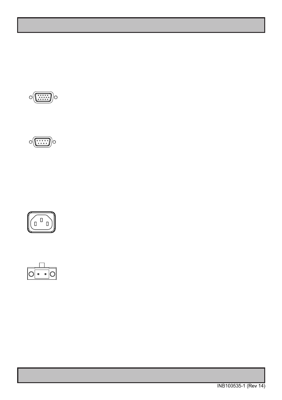
VGA/RGB IN:
Connect your VGA cable to the D-SUB 15P Connectors (female). Secure the VGA cable to the hex spacers provided
on the unit and make sure you do not bend any of the pins inside the connector when connecting. Connect the other
end of the cable to the VGA connector on your equipment and secure it.
RS-232 COM I/O:
This 9P COM connector provides additional functionality for the unit. The Serial Remote Control features a RS-232
(non-isolated) interface for controlling internal parameters like brightness. You can access most of the parameters
available in the OSD menu and with special commands control the unit externally. This COM can also be used to
upgrade the firmware for the graphic controller inside the unit which is available on request and through service
channels (for qualified personnell only). Fasten your external cable to the D-SUB 9P Male connector using the
provided screws on the cable housing.
Please review “Management Settings/Communication” in the “OSD Menu Functions” chapter for more information.
POWER INPUT:
The internal AC power module supports both 115VAC/60Hz and 230VAC/50Hz power input. Please check
specifications for your unit.
- +
POWER INPUT:
Connect your DC power cable to the 2-pin Terminal Block 5.08 connector. The internal DC power module supports
24VDC. For more information, please review “Housing Connector Overview” earlier in this manual.