Standard cable pinouts, Pin 1 pin 10 – Datalogic Scanning QUICKSCAN QD2100 User Manual
Page 277
Standard Cable Pinouts
Product Reference Guide
269
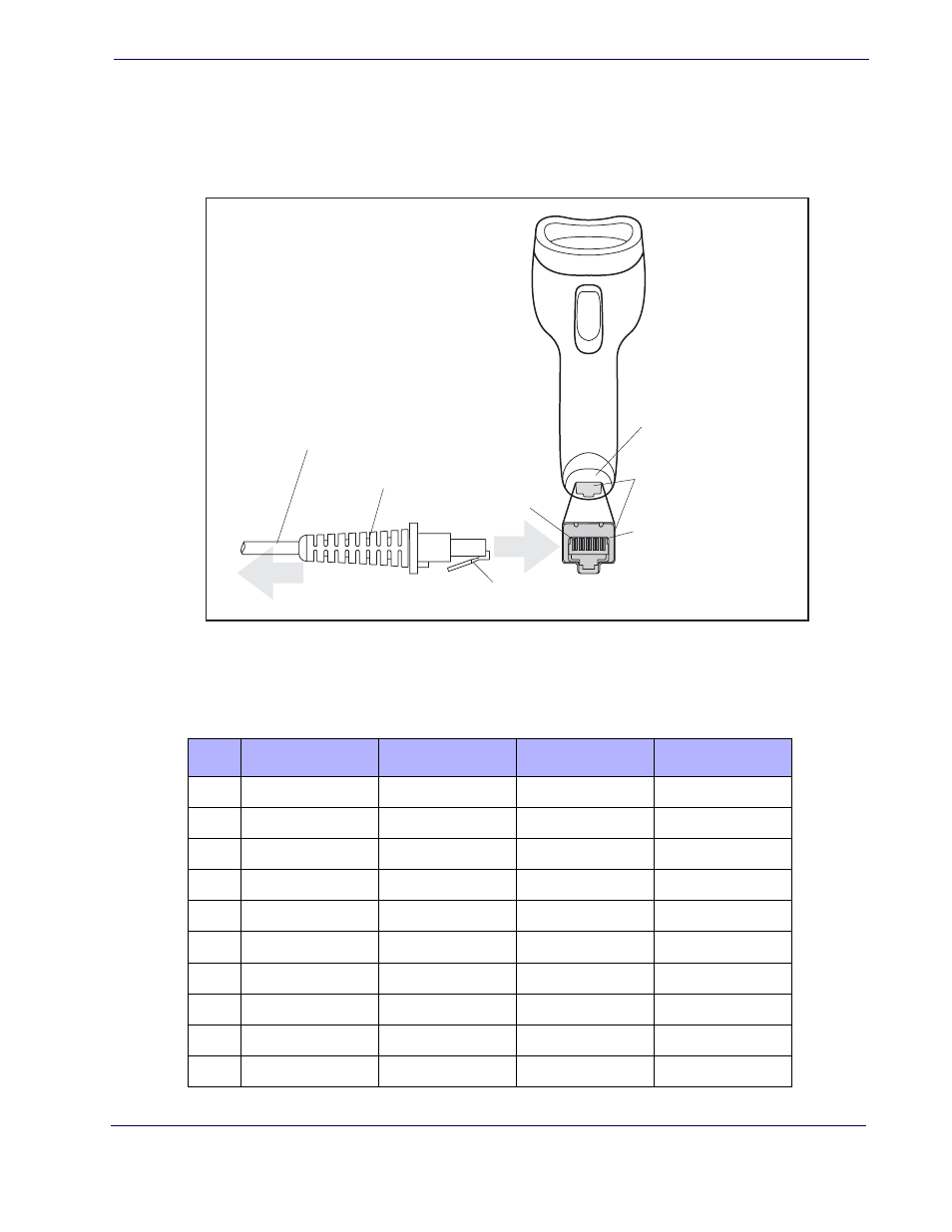
Standard Cable Pinouts
Figure 7
and
Table 36
provide standard pinout information for the imager’s cable.
Figure 7. Standard Cable Pinouts
The signal descriptions in
Table 36
apply to the connector on the imager and are for ref-
erence only.
Table 36. Standard Cable Pinouts — Imager Side
Cable Clip (Latch)
To Host
Cable
Cable Strain Relief
Bottom of Imager
Interface Cable Port
Pin 1
Pin 10
Pin
RS-232
OEM
USB
Keyboard Wedge
1
RTS (out)
2
D+
CLKIN (KBD side)
3
D-
DATAIN (KBD side)
4
GND
GND
GND
GND
5
RX
6
TX
7
VCC
VCC
VCC
VCC
8
IBM_B
CLKOUT (PC side)
9
IBM_A
DATAOUT (PC side)
10
CTS (in)