10 system panel (f_panel) – Avalue ERX-Q77 User Manual
Page 44
ERX-Q77
User’s Manual
44 ERX-Q77
User’s Manual
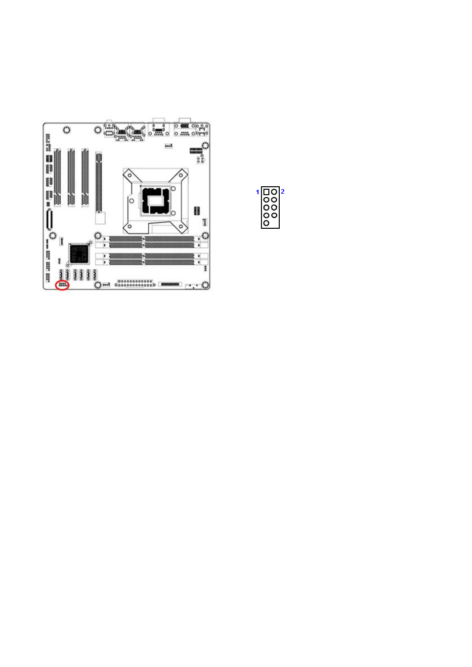
2.8.10 System Panel (F_PANEL)
This connector is for a chassis-mounted front panel audio I/O module that supports either HD
Audio o
r legacy AC’97 audio standard.
1. HDD_LED+
3. SATA_LED#
5. GND
7.
SRST#
9. NC
2. +V5_DUAL
4. SUPLED1
6. PANSWIN#
8. GND
ATX Power Button/Soft-off Button (Pin 6-8)
This 2-pin connector is for the system power button. Pressing the power button turns the
system on or puts the system in sleep or soft-off mode depending on the BIOS settings.
Pressing the power switch and holding it for more than four seconds while the system is
ON turns the system OFF.
Reset Button (Pin 5-7)
This 2-pin connector is for the chassis-mounted reset button for system reboot without
turning off the system power.
Power LED (Pin 2-4)
This 2-pin connector is for the system power LED. Connect the chassis power LED cable
to this connector. The system power LED lights up when you turn on the system power,
and blinks when the system is in sleep mode.
Hard Disk Drive Activity LED (Pin 1-3)
This 2-pin connector is for the HDD Activity LED. Connect the HDD Activity LED cable to
this connector. The IDE LED lights up or flashes when data is read from or written to the
HDD.