Pc/104 bus interface – ADLINK CM3-GF User Manual
Page 53
TME-104P-CMx-GF-1V7
Rev 1.7
45 (81)
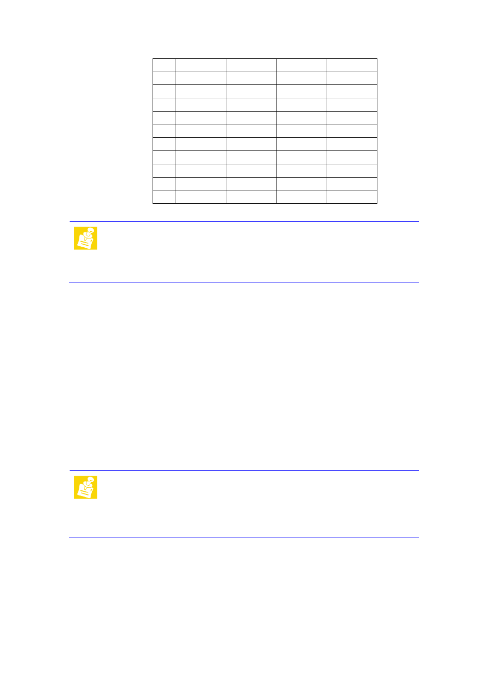
Note:
All VI/O pins are connected to +3.3V.
The voltages +5V, +12V and -12V are not generated by the on-board
power supply but routed from the power supply connector. The
maximum current is limited to 1.0A for each
voltage
.
3.16 PC/104 Bus Interface
The PC/104 bus is a modification of the industry standard (ISA) PC bus specified in IEEE P996. The PC/104 bus
has different mechanics than P966 to allow the stacking of modules. The main features are:
Supports programmable extra wait state for ISA cycles
Supports I/O recovery time for back-to-back I/O cycles
The following table shows the pin assignments of the PC/104 connector.
Note:
-5 V on the PC/104 connector are not supported on this board.
The voltages +5V, +12V and -12V are not generated by the on-board
power supply but routed from the power supply connector. The
maximum current is limited to 1.0A for each
voltage.
20
GND
AD26
AD25
GND
21
AD29
+5V
AD28
AD27
22
+5V
AD30
GND
AD31
23
REQ0#
GND
REQ1#
VI/O
24
GND
REQ2#
+5V
GNT0#
25
GNT1#
VI/O
GNT2
GND
26
+5V
CLK0
GND
CKL1
27
CLK2
+5V
CLK3
GND
28
GND
INTD#
+5V
RST#
29
+12V
INTA#
INTB#
INTC#
30
-12V
REQ3#
GNT3#
GND