Reset button, Speaker – ADLINK CM3-GF User Manual
Page 39
TME-104P-CMx-GF-1V7
Rev 1.7
31 (81)
Pin
Signal
Pin
Signal
1
Speaker
2
Mouse Clock
3
Reset-In
4
Mouse Data
5
KB Data
6
KB Clock
7
GND
8
+5V Standby
9
Ext. Battery
10
Power Button
Reset Button
To reset the board, the signal Reset Button must be pulled to GND.
Pin
Signal
Pin
Signal
1
Speaker
2
Mouse Clock
3
Reset-In
4
Mouse Data
5
KB Data
6
KB Clock
7
GND
8
+5V Standby
9
Ext. Battery
10
Power Button
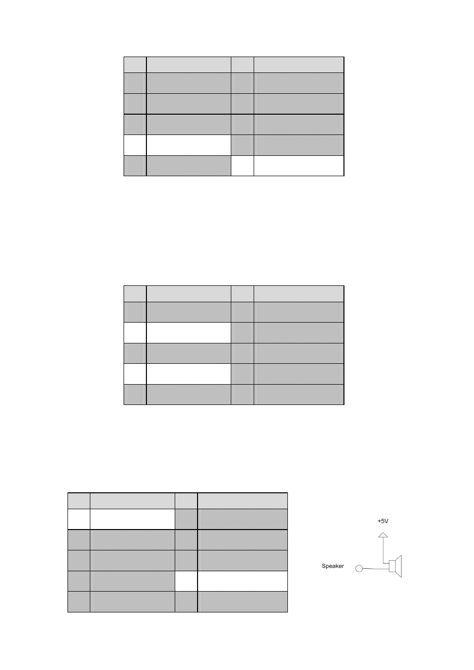
Speaker
The speaker signal is located on the PS/2, IDC10 Header. A standard PC Speaker can be connected between
the signals Speaker and +5V Standby.
Pin
Signal
Pin
Signal
1
Speaker
2
Mouse Clock
3
Reset-In
4
Mouse Data
5
KB Data
6
KB Clock
7
GND
8
+5V Standby
9
Ext. Battery
10
Power Button
This manual is related to the following products: