Lvds configuration, Lvds connector (x13) – ADLINK CM3-GF User Manual
Page 32
TME-104P-CMx-GF-1V7
Rev 1.7
24 (81)
LVDS Configuration
To ease usage of these displays it is possible to select the display and backlight supply voltages with the
onboard voltage selector jumpers (LVDS and Backlight.) See below.
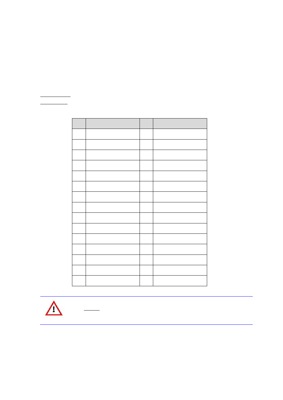
LVDS Connector (X13)
Connector type
Hirose DF14 30-pin header
Adapter cable
n/a
Pin
Signal
Pin
Signal
1
VCC_LCD
2
VCC_LCD
3
GND
4
GND
5
LVDS_L3n
6
LVDS_L3p
7
LVDS_LCLKn
8
LVDS_LCLKp
9
GND
10
LVDS_L2n
11
LVDS_L2p
12
LVDS_L1n
13
LVDS_L1p
14
LVDS_L0n
15
LVDS_L0p
16
GND
17
LVDS_U3n
18
LVDS_U3p
19
LVDS_UCLKn
20
LVDS_UCLKp
21
GND
22
LVDS_U2n
23
LVDS_U2p
24
LVDS_U1n
25
LVDS_U1p
26
LVDS_U0n
27
LVDS_U0p
28
GND
29
LVDS_DDC_CLK
30
LVDS_DDC_DATA
Caution
The maximum current on all supply pins is 1A.
This manual is related to the following products: