Lvds color mapping, Backlight connector (x5) – ADLINK CM3-GF User Manual
Page 33
TME-104P-CMx-GF-1V7
Rev 1.7
25 (81)
LVDS Color Mapping
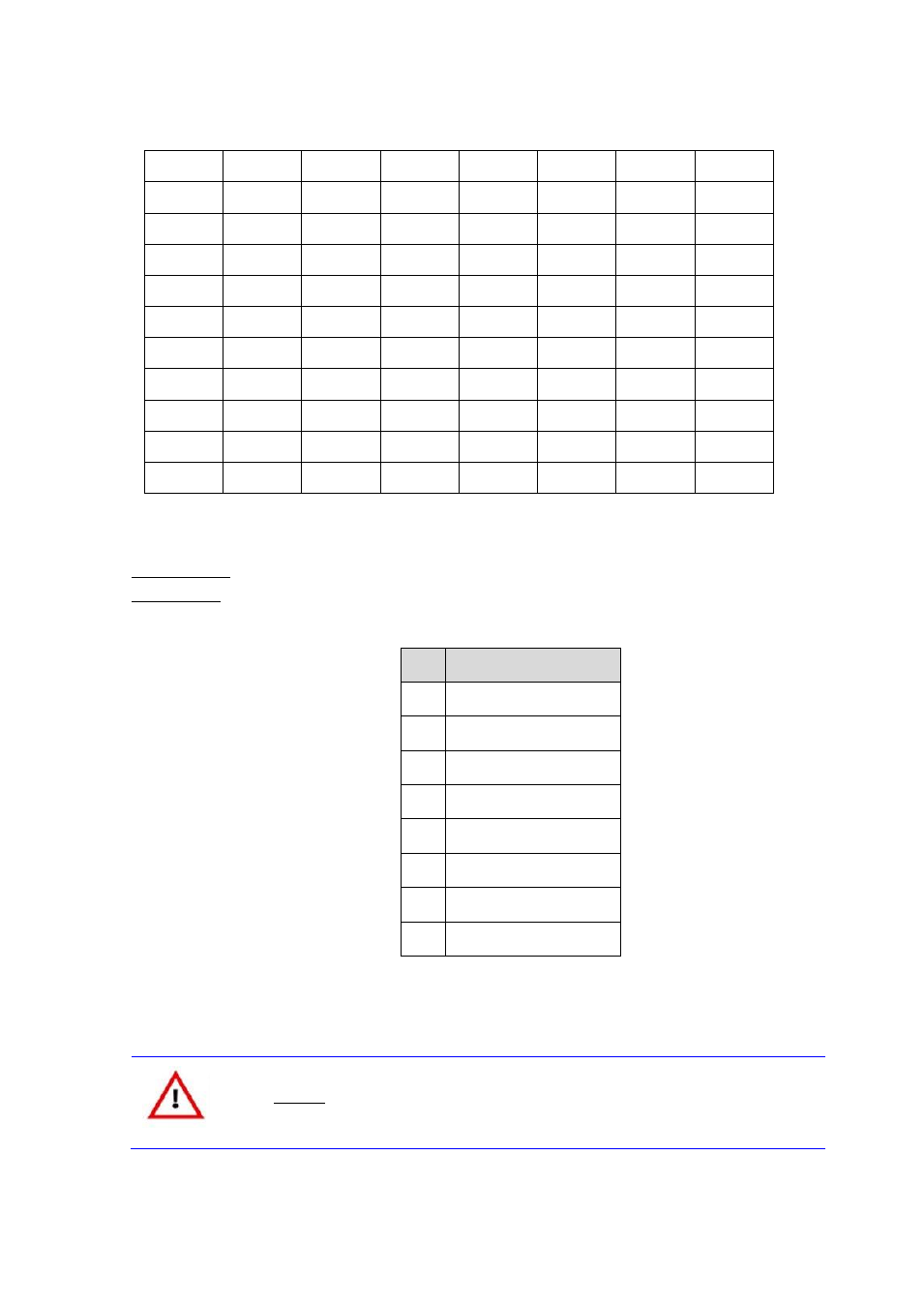
Backlight Connector (X5)
Connector type
Hirose DF13, 8-pin
Adapter cable
n/a
Pin
Signal
1
+12V
2
+12V
3
+5V
4
+5V
5
EN
6
VCC*
7
GND
8
GND
*That voltage can be selected using the jumper "Backlight", shown on next table.
Caution
The maximum current on all supply pins is 1A.
1
2
3
4
5
6
7
CLKL
1
1
0
0
0
1
1
L0
Green2
Red7
R6
R5
R4
R3
R2
L1
Blue3
B2
G7
G6
G5
G4
G3
L2
DE
VS
HS
B7
B6
B5
B4
L3
0/B1
B1
B0
G1
G0
R1
R0
CLKU
1
1
0
0
0
1
1
U0
G2
R7
R6
R5
R4
R3
R2
U1
B3
B2
G7
G6
G5
G4
G3
U2
DE
VS
HS
B7
B6
B5
B4
U3
0/B1
B1
B0
G1
G0
R1
R0
This manual is related to the following products: