Single-node redundant signaling server, Ip network configuration – Dialogic TX4000 PCI SS7 User Manual
Page 35
TX 4000 PCI SS7 Network Interface Board Installation Manual
Establishing network connections
Single-node redundant signaling server
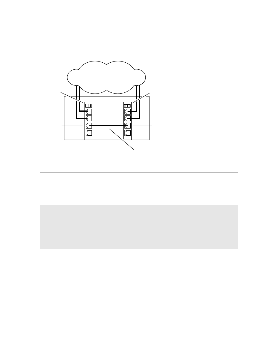
The following illustration shows how to set up two TX 4000 boards based on the
single-node signaling server in a TDM configuration. The boards are located in the
same chassis to ensure board-level redundancy.
SS7 links
TX 4000
(primary)
Chassis 1
Private Ethernet connection
Ethernet 1
Ethernet 1
TX 4000
(backup)
IP network configuration
To connect a TX 4000 board to its redundant mate in an IP network configuration,
use a Category 5 shielded twisted pair (STP) crossover cable. Using the crossover
cable, connect Ethernet 1 on the primary board to Ethernet 1 on the backup board.
Using standard Ethernet cables, connect the Ethernet 2 connectors on both boards to
the IP network connectors.
Note: Dialogic recommends using a private Ethernet link to connect the redundant
boards to avoid loss or delay of vital checkpoint messages. However, if each board in
the redundant pair requires multi-homing, you can use Ethernet 1 for both the
redundant pathway and for SIGTRAN network access. In this configuration, the
Ethernet 1 on each board is connected to what is shown as an IP network cloud in
the illustrations that follow (just as the Ethernet 2 connectors are). Be aware that
this greatly increases the chance of lost or delayed checkpoint messages which can
result in the backup having outdated information.
You must specify the IP address of the TX board’s redundant mate using the mate
command in the txconfig utility. You must also define the IP interface address using
the ifcreate command (for interface 1) in the txconfig utility. For more information,
refer to the Dialogic® NaturalAccess™ Signaling Software Configuration Manual.
Dialogic Corporation
35