Connecting tx boards for redundancy, Tdm configuration, Dual-node redundant signaling server – Dialogic TX4000 PCI SS7 User Manual
Page 34: Ge 34
Establishing network connections
TX 4000 PCI SS7 Network Interface Board Installation Manual
Connecting TX boards for redundancy
Use the redundancy feature to enable the system to detect and recover from the
failure of signaling links on a TX 4000 board, the failure of a signaling node, or the
failure of the TX 4000 board itself.
In a redundant configuration, each pair of TX boards is connected through a private
Ethernet connection. If other devices are connected to the private Ethernet link,
avoid overloading the link. Packets can be lost between the redundant TX boards if
the connection is overloaded.
This topic describes dual-node redundant signaling and single-node redundant
signaling for the following types of configurations:
• TDM configuration
• IP network configuration
TDM configuration
To connect a TX 4000 board to its redundant mate in a TDM configuration, use a
Category 5 shielded twisted pair (STP) crossover cable. With the crossover cable,
connect Ethernet 1 on the primary board to Ethernet 1 on the backup board.
You must specify the IP address of the TX board’s redundant mate using the mate
command in the txconfig utility. You must also define the IP interface address using
the ifcreate command (for interface 1) in the txconfig utility. For more information,
refer to the Dialogic® NaturalAccess™ Signaling Software Configuration Manual.
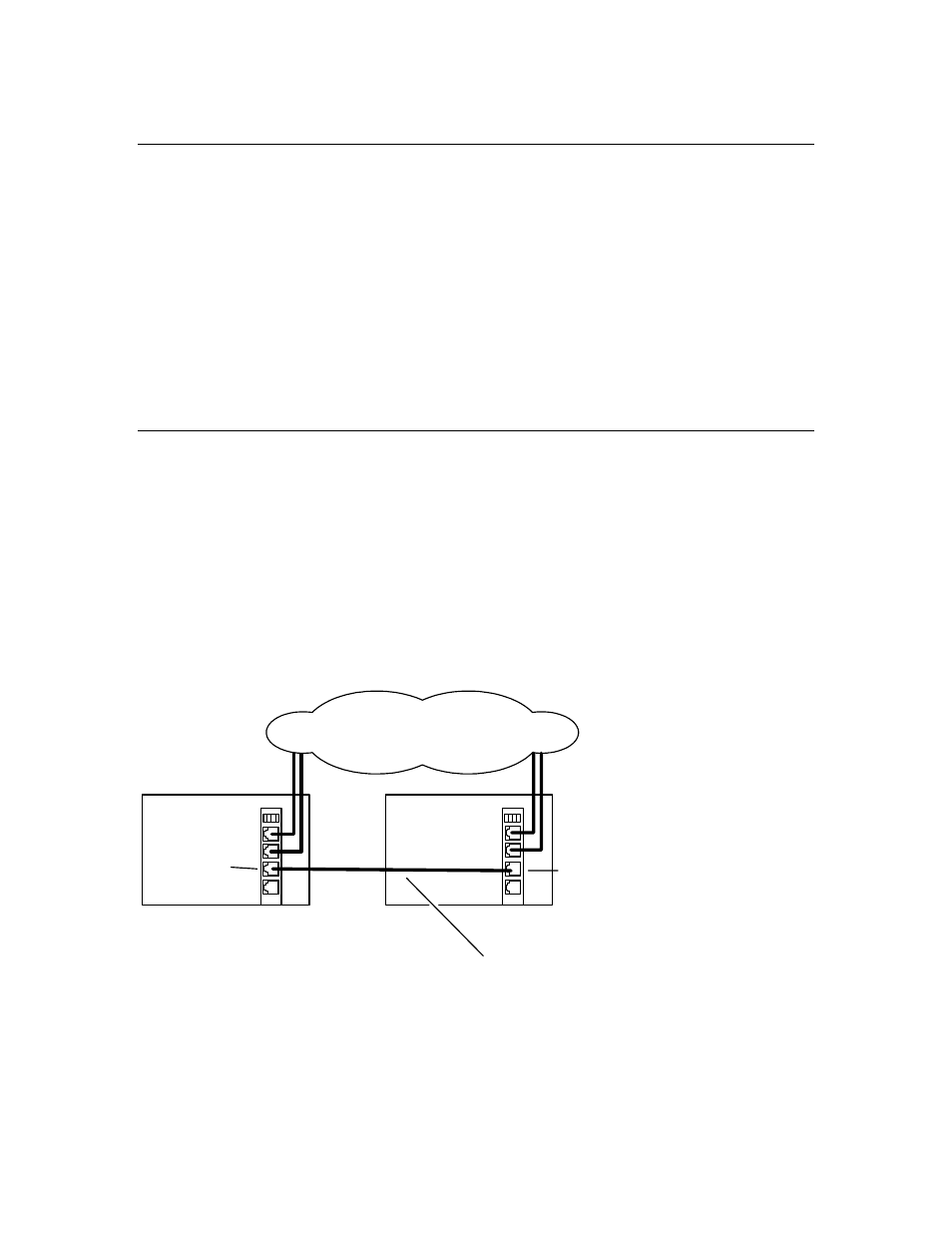
Dual-node redundant signaling server
The following illustration shows how to set up two TX 4000 boards based on a dual-
node redundant signaling server in a TDM configuration. The boards are located in
two separate chassis to ensure board-level and system-level redundancy.
Chassis 1
with TX 4000
(primary)
Chassis 2
with TX 4000
(backup)
SS7 links
Private Ethernet connection
Ethernet 1
Ethernet 1
34
Dialogic Corporation