3 specifications, Specifications – ADLINK PCI-9810 User Manual
Page 14
2
Introduction
1.3
Specifications
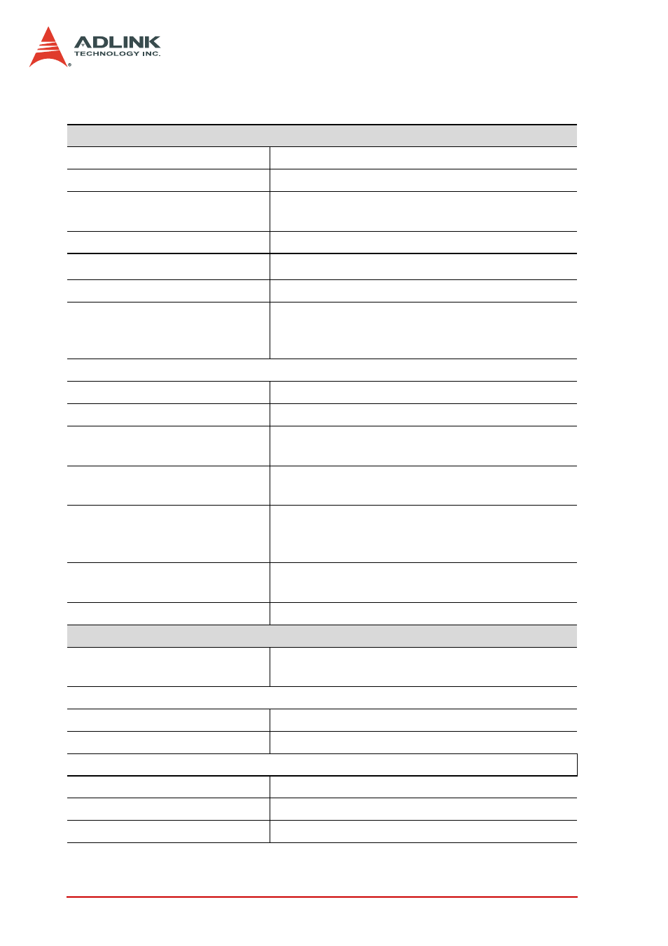
Analog Input (AI)
Converters
B.B. ADS800 series
Input Channels
Four single-ended
Resolution
12-bit (PCI-9812)
10-bit (PCI-9810)
Over Voltage Protection
Bipolar ±1 V, or ±5 V by soldering selection
Maximum Sampling Rate
1
20 MHz samples/second
Accuracy
Gain error ±1.5% at 25°C
Input Impedance (soldering
selectable)
50
Ω (±1 V and ±5 V)
1.25 K
Ω (±5 V only)
5 M
Ω (±1 V only)
Dynamic Characteristic
Differential Linearity Error
±0.4 LSB (Typ.) ±1.0 LSB (Max.) at 25°C
Integral Linearity Error
±1.9 LSB at 25°C
A/D Clock Sources
Internal clock, continuous external digital clock,
and continuous external sine wave
Input Impedance of External
Clock Source
50
Ω
Trigger Sources
Software, analog threshold comparator using
internal D/A to set trigger level, and external
digital trigger
Trigger Modes
Software-trigger, pre-trigger, post-trigger,
middle-trigger, and delay-trigger
AD Data Transfer Method
DMA (bus mastering)
Digital Input (DI)
Channels
Three TTL compatible inputs with 10 KW pull
down resistor
Input Voltage
Low
Min. 0 V, Max. 0.8 V
High
Min. +2.0 V, Max. 5.5 V
Input Load
Low
±1 uA 0 V
0.5 mA 5V
High
+2.7V min. 20 mA max.