Figure 1-10, Clock source indicators – ADLINK PXIS-2719A User Manual
Page 26
16
Introduction
Priority of the 10MHz reference clock is as shown.
Table 1-6: 10MHZ Reference Clock Priority
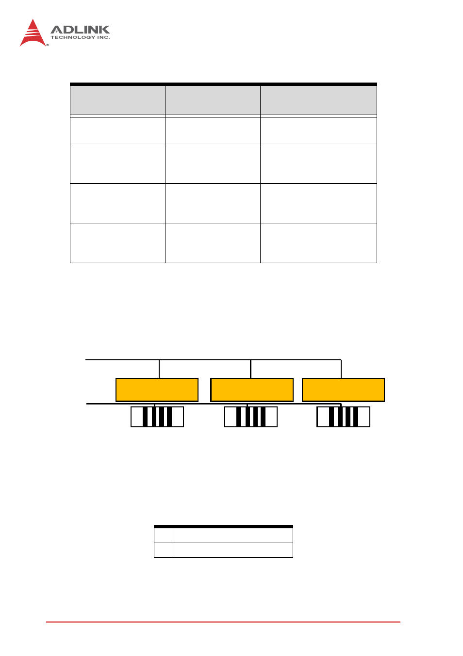
Three indicators on the backplane indicate the 10MHz clock
source driven to all peripheral slots, as shown.
Figure 1-10: Clock Source Indicators
Table 1-7: Clock Source Indicators Legend
System Timing
Slot (2nd slot)
BNC connector on
rear panel
10MHz clock driven to
peripheral slots
No clock present
No clock present
The 10MHz clock is
generated by backplane.
No clock present
10MHz clock
present
Clock from BNC
connector is driven to all
the peripheral slots
10MHz clock
present
No clock present
Clock from system
timing slot is driven to all
the peripheral slots
10MHz clock
present
10MHz clock
present
Clock from system
timing slot is driven to all
the peripheral slots
A
LEDs
B
Resistors
LED1
R300
LED2
R301
LED3
R302
A
B
- USB-1901 (84 pages)
- USB-1210 (54 pages)
- USB-2401 (60 pages)
- USB-7230 (50 pages)
- USB-2405 (56 pages)
- DAQe-2010 (92 pages)
- DAQe-2204 (100 pages)
- DAQe-2213 (94 pages)
- DAQe-2501 (74 pages)
- PXI-2010 (84 pages)
- PXI-2020 (60 pages)
- PXI-2501 (62 pages)
- cPCI-9116 (98 pages)
- ACL-8112 Series (92 pages)
- ACL-8112 Series (93 pages)
- ACL-8112 Series (94 pages)
- ACL-8216 (75 pages)
- ACL-8111 (61 pages)
- PCM-9112+ (10 pages)
- PCM-9112+ (94 pages)
- cPCI-6216V (47 pages)
- ACL-6126 (28 pages)
- ACL-6128A (40 pages)
- PCM-6308V+ (52 pages)
- PCM-6308V+ (4 pages)
- PCI-7444 (82 pages)
- PCI-7434 (48 pages)
- PCI-7234 (56 pages)
- PCI-7260 (66 pages)
- PCI-7258 (38 pages)
- PCI-7256 (48 pages)
- PCI-7250 (48 pages)
- LPCI-7250 (48 pages)
- PCI-7396 (65 pages)
- PCI-7296 (59 pages)
- PCI-8554 (67 pages)
- PCIe-7360 (94 pages)
- PCIe-7350 (86 pages)
- PCIe-7300A (114 pages)
- PCIe-7200 (51 pages)
- PCI-7300A (112 pages)
- PCI-7300A (83 pages)
- PCI-7200 (96 pages)
- cPCI-7300 (82 pages)
- cPCI-7300 (83 pages)