ADLINK ACL-8454/12 User Manual
Page 23
Installation & Configurations
• 15
Independent Counters (Counter #1~#4, & Counter #7~#10)
The Counter #1 to Counter #4 and Counter #7 to Counter #10 are
independent because the clock source and gate control of those counters
can be set independently. These 8 counters are named as independent
counters.
CLK1
COUT1
GATE1
Counter #1
8254 Chip #1
C
G
O
Figure 2.9 Example of ‘independent counters’
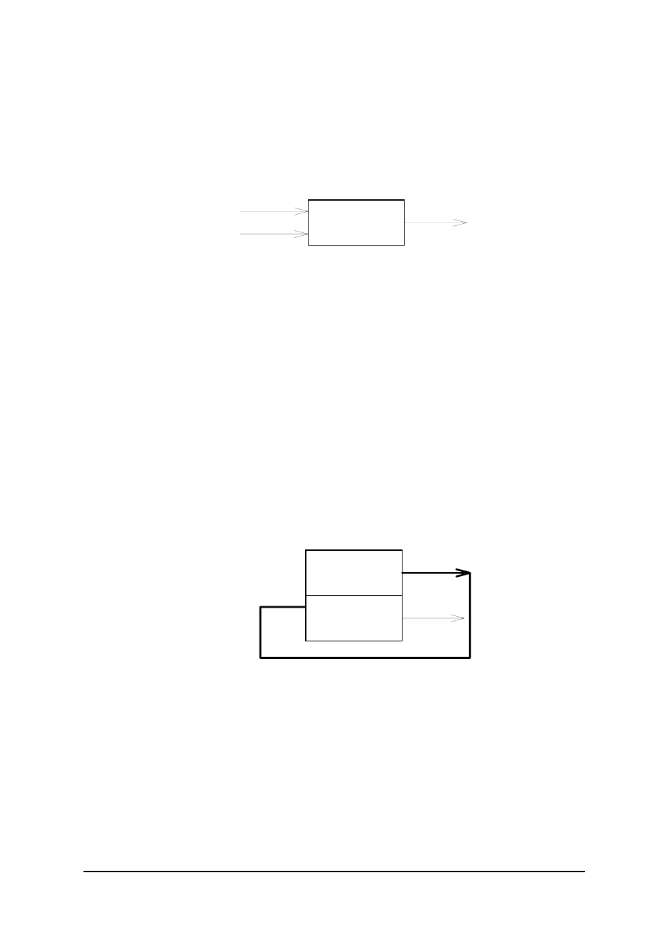
Cascaded Counters
The connection of Counter #5, #6 and Counter #11, #12 are different with
other independent counters. These four counters are named as cascaded
counters because the clock sources of counter #5 and #11 come from fixed
1 MHz and their output are cascaded to counter #6 and #12 respectively. In
fact, counter #5, #6 and counter #11, #12 are designed for frequency
divider by using 8254's square wave generator mode. The gates of these
counters keep at 'H' level for enabling counters all the time. The COUT6
and COUT12 can precisely generate frequency upper to 250 KHz and lower
to 0.000233 Hz. Note that the signals COUT6 and COUT12 can also be
used as interrupt source. See ‘Interrupt Sources’ section for details. The
following figure demonstrates a set of cascaded counter - counter #5 and
#6.
1 MHz
COUT5
Counter #5
COUT5
COUT6
Counter #6
8254 Chip #2
C
G
C
G
O
O
'H'
'H'
Figure 2.10 Example of ‘cascaded counter’
User Configurable Cascaded Counters
Although there are two cascaded counter on board, users may need more
cascaded counters. User can configure the jumper for the clock source of
every independent counter. Therefore, the independent counter output can
be cascaded to the next counter's clock source by jumper setting. Figure
2.11 demonstrates an example of the user configurable cascaded counter.
Refer to next section for details of the clock source setting.
Multi-Configurations