4 default jumper setting – ADLINK PCI-8554 User Manual
Page 19
Getting Started •9
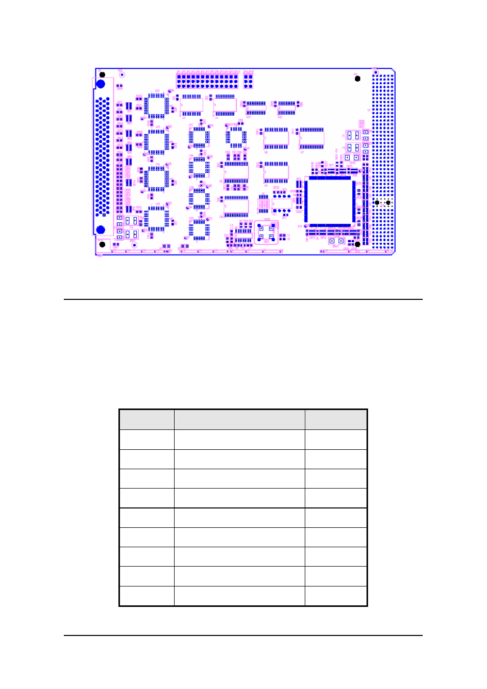
Figure 3: PCB Layout of cPCI-8554/R
2.4
Default Jumper Setting
To operate the cPCI/PCI-8554/R correctly, users need to understand the
structure of cPCI/PCI-8554/R and details of the possible configurations.
The functional block diagram of the cPCI/PCI-8554/R is shown in figure 1
of chapter 1. The following section lists the default jumper setting on the
cPCI/PCI-8554/R.
Items
Default Configuration
Set by
ECLK1
No Debounce function
JP1
ECLK2
No Debounce function
JP2
ECLK3
No Debounce function
JP3
ECLK4
No Debounce function
JP4
ECLK5
No Debounce function
JP5
ECLK6
No Debounce function
JP6
ECLK7
No Debounce function
JP7
ECLK8
No Debounce function
JP8
ECLK9
No Debounce function
JP9
See also other documents in the category ADLINK Hardware:
- USB-1901 (84 pages)
- USB-1210 (54 pages)
- USB-2401 (60 pages)
- USB-7230 (50 pages)
- USB-2405 (56 pages)
- DAQe-2010 (92 pages)
- DAQe-2204 (100 pages)
- DAQe-2213 (94 pages)
- DAQe-2501 (74 pages)
- PXI-2010 (84 pages)
- PXI-2020 (60 pages)
- PXI-2501 (62 pages)
- cPCI-9116 (98 pages)
- ACL-8112 Series (93 pages)
- ACL-8112 Series (94 pages)
- ACL-8112 Series (92 pages)
- ACL-8216 (75 pages)
- ACL-8111 (61 pages)
- PCM-9112+ (10 pages)
- PCM-9112+ (94 pages)
- cPCI-6216V (47 pages)
- ACL-6126 (28 pages)
- ACL-6128A (40 pages)
- PCM-6308V+ (52 pages)
- PCM-6308V+ (4 pages)
- PCI-7444 (82 pages)
- PCI-7434 (48 pages)
- PCI-7234 (56 pages)
- PCI-7260 (66 pages)
- PCI-7258 (38 pages)
- PCI-7256 (48 pages)
- PCI-7250 (48 pages)
- LPCI-7250 (48 pages)
- PCI-7396 (65 pages)
- PCI-7296 (59 pages)
- PCIe-7360 (94 pages)
- PCIe-7350 (86 pages)
- PCIe-7300A (114 pages)
- PCIe-7200 (51 pages)
- PCI-7300A (112 pages)
- PCI-7300A (83 pages)
- PCI-7200 (96 pages)
- cPCI-7300 (83 pages)
- cPCI-7300 (82 pages)