A2.5 circuits and wiring – ADLINK PCI-7396 User Manual
Page 62
54
• Appendix 2 DIN-96DO
Legend:
CN1 : SCSI II 100 pin connector to connect PCI-7396 and DIN-96DO
X1~X4 : 50 pin Opto-22 connectors to connect TB96 and Tb96DO
n(1~96) : Output signal n
G : External ground
P : External power (5~24V)
A2.5 Circuits and Wiring
The connection of isolated digital output is shown as the following diagram.
The DIN-96DO need external 5~24V DC power from the POWER pin to
provide the power source of the digital output circuit. The POWER pin is
used as “fly-wheel” diode, which can protect the driver if the loading is
inductance loading such as relay, motor or solenoid. If the loading is
resistance loading such as resistor or LED, the connection to fly-wheel diode
is not necessary.
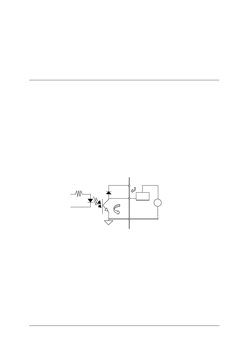
Therefore, the first step for connecting the output with external device is to
distinguish the type of loading. For example, if the loading is LED or resistor,
you can use the following wiring diagram.
+
-
D D
V
Resistive
Loading
5~24V
-
GND
Power
Figure A2.1: opto-isolated output circuit for resistance loading