ADLINK PCI-7396 User Manual
Page 36
28
• Operation Theorem
4.3.4
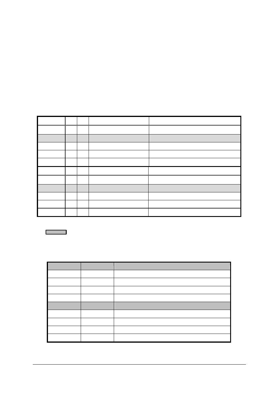
Interrupt Source Control (ISC)
There are four bits to control the IRQ sources of INT1 and INT2. Table 4.1
shows the selection of the IRQ sources and the interrupt trigger condition.
If the application needs one IRQ only, you can disable one of the IRQ
sources by software. You can also disable both the two interrupts If you do
not need any IRQ source. However, the PCI BIOS still assign a IRQ level to
the PCI card and occupy the PC resource if you only disable the IRQ
sources without change the initial condition of the PCI controller.
INT1
C1 C2 IRQ Sources
IRQ Trigger Condition
Disable
4
X
INT1 disable
--
Mode 1
0
X
COS P1&P2 (48bits) Change of State for PCI-7396
Mode 2
1
X
P1C0 OR ~P1C3
(see following)
Mode 3
2
X
~P1C0
falling edge of P1C0
Mode 4
3
X
Event Counter
Counter count down to 0
INT2
C1 C2 IRQ Sources
IRQ Trigger Condition
Disable
X
4
INT2 disable
--
Mode 1
X
0
COS P3&P4 (48bits) Change of State for PCI-7396
Mode 2
X
1
P2C0 OR ~P2C3
(see following)
Mode 3
X
2
~P2C0
falling edge of P2C0
Mode 4
X
3
Timer Output
Timer count down to 0
Table 4.1 ISC register format
Default settings
When the IRQ sources is set as “P1C0 OR ~P1C3” or “P2C0 OR ~P2C3”,
the IRQ trigger conditions are summarized in Table 4.2,
P1C0
P1C3
IRQ Trigger Condition
High
X
P1C0=‘H’ disable all IRQ
X
Low
P1C3=‘L’ disable all IRQ
Low
1->0
P1C3 falling edge trigger when P1C0=L
0->1
High
P1C0 rising edge trigger when P1C3=H
P2C0
P2C3
IRQ Trigger Condition
High
X
P2C0=‘H’ disable all IRQ
X
Low
P2C3=‘L’ disable all IRQ
Low
1->0
P2C3 falling edge trigger when P2C0=L
0->1
High
P2C0 rising edge trigger when P2C3=H
Table 4.2 IRQ Trigger conditions