A1.5 di circuits and wiring – ADLINK PCI-7396 User Manual
Page 58
50
• Appendix 1 DIN-96DI
Legend:
CN1 : SCSI II 100 pin connector to connect PCI-7396 and DIN-96DI
X1~X4 : 50 pin Opto-22 connectors to connect TB96 and Tb96DI
n(1~96) : Input signal n
G : External ground
P : External power (5~24V)
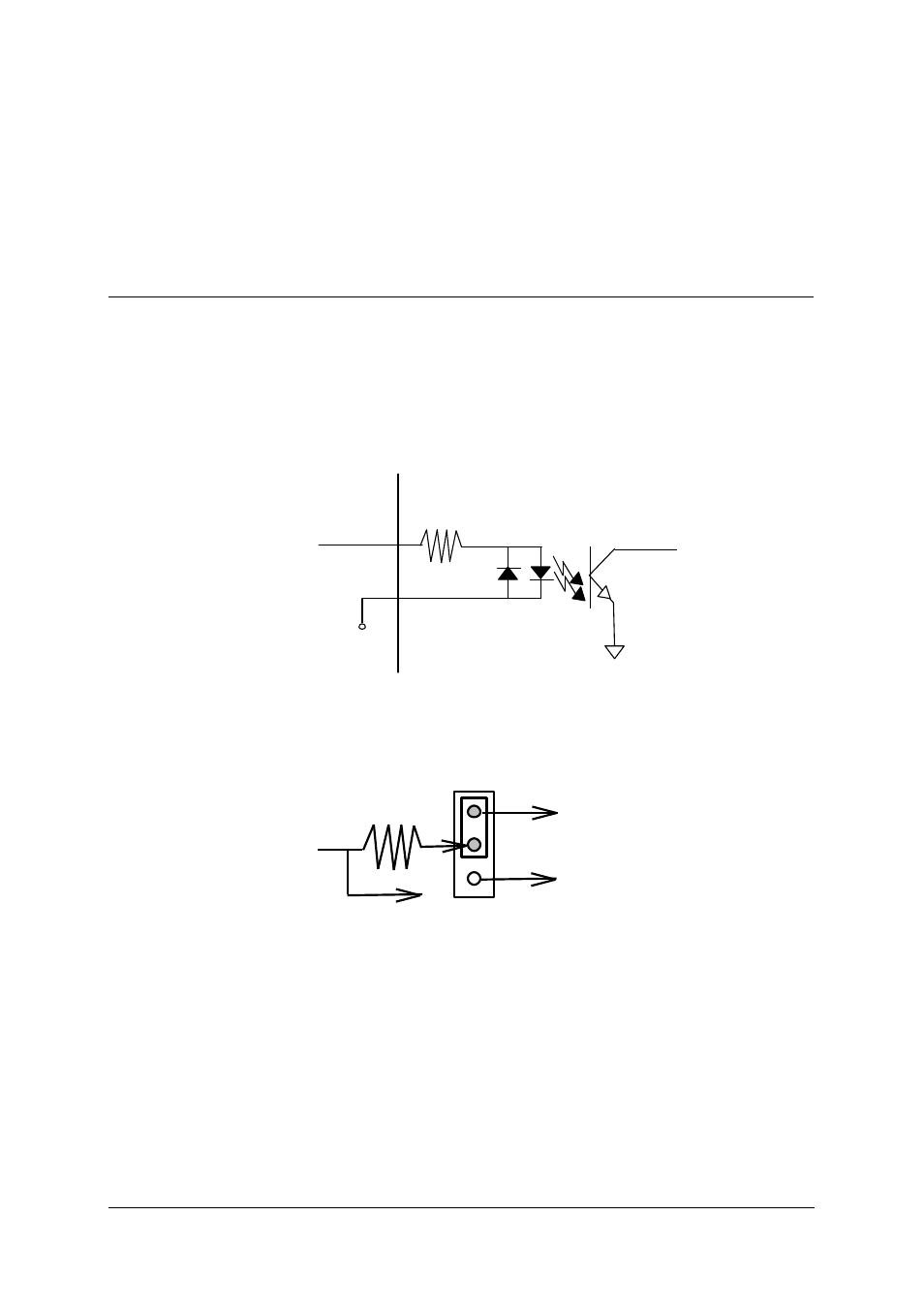
A1.5 DI Circuits and Wiring
The outputs of the opto-isolated digital input circuits are open collector
transistors. PCI-7396 should provide pull-high resistors by correct jumper
setting. The connection between outside signal and PCI-7396 as well as the
jumper setting are shown below.
2.4K Ohm
Power 24V
Input
PCI-7396
DIn
Figure A1.1: opto-isolated input circuit
PCI-7396
DIn
JPxx
Vcc
GND
TTL Device
Figure A1.2: PCI-7396 jumper setting for DIN-96DI
See also other documents in the category ADLINK Hardware:
- USB-1901 (84 pages)
- USB-1210 (54 pages)
- USB-2401 (60 pages)
- USB-7230 (50 pages)
- USB-2405 (56 pages)
- DAQe-2010 (92 pages)
- DAQe-2204 (100 pages)
- DAQe-2213 (94 pages)
- DAQe-2501 (74 pages)
- PXI-2010 (84 pages)
- PXI-2020 (60 pages)
- PXI-2501 (62 pages)
- cPCI-9116 (98 pages)
- ACL-8112 Series (92 pages)
- ACL-8112 Series (93 pages)
- ACL-8112 Series (94 pages)
- ACL-8216 (75 pages)
- ACL-8111 (61 pages)
- PCM-9112+ (10 pages)
- PCM-9112+ (94 pages)
- cPCI-6216V (47 pages)
- ACL-6126 (28 pages)
- ACL-6128A (40 pages)
- PCM-6308V+ (52 pages)
- PCM-6308V+ (4 pages)
- PCI-7444 (82 pages)
- PCI-7434 (48 pages)
- PCI-7234 (56 pages)
- PCI-7260 (66 pages)
- PCI-7258 (38 pages)
- PCI-7256 (48 pages)
- PCI-7250 (48 pages)
- LPCI-7250 (48 pages)
- PCI-7296 (59 pages)
- PCI-8554 (67 pages)
- PCIe-7360 (94 pages)
- PCIe-7350 (86 pages)
- PCIe-7300A (114 pages)
- PCIe-7200 (51 pages)
- PCI-7300A (112 pages)
- PCI-7300A (83 pages)
- PCI-7200 (96 pages)
- cPCI-7300 (82 pages)
- cPCI-7300 (83 pages)