4 configuring jumper settings, Removing the top cover – Dolby Laboratories DP503 User Manual
Page 27
3-3
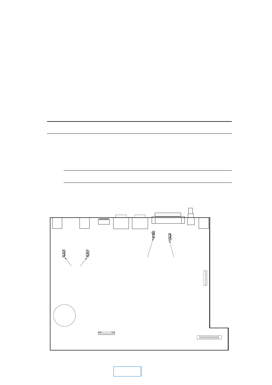
3.4
Configuring Jumper Settings
The Model DP503 includes certain user-selectable options that are configured by
means of internal jumpers, as shown below. Their default settings (shipped with
the unit) are shown in the figure. Any jumpers not specifically mentioned are for
factory use only and should not be disturbed.
Removing the Top Cover
If you need to gain access to the interior of the DP503 to change these jumpers,
remove the top cover of the unit as follows:
WARNING:
Be sure that the unit is NOT powered up. As there is no power switch, the power cord must
not be connected.
Using the supplied hex wrench, remove the 12 screws securing the top
cover to the chassis; there are three screws on the upper front panel, upper
rear panel, and each of the sides. The three washerless screws should be
reserved for affixing at the top of the front panel when re-assembling the
unit.
Note:
The front panel is attached to the chassis by means of 3 screws at the lower portion of the
front panel. These do not need to be disturbed in order to remove the top cover.
Gently lift the top cover upward and towards the rear. Carefully set aside.
Reverse the above procedure when re-assembling the unit.
Signal ground to
chassis ground link
ST input clock
termination (150 ohm)
TERMINATED
NOT TERMINATED
600
10K
600
10K
J13
J14
J14
J12
LINKED
OPEN
Audio input
termination
DP503 MOTHERBOARD
S101
ChB
ChA
MAIN