Exhaust duct and air intake – American Dryer Corp. AD-100 User Manual
Page 50
Attention! The text in this document has been recognized automatically. To view the original document, you can use the "Original mode".
Minimum
for I2"dia. ducts
for l6“dio ducts
670
560
450
340
230
115
1230
1025
820
615
410
205
R6URE I
FIGURE 2
To calculate area (in square inches) of round ducting:
Area = diameter (in inches)
X
Diameter (in inches) x .785. (Example:
area of 12" diameter duct = 12 x 12 x
.785 = 113 square inches.)
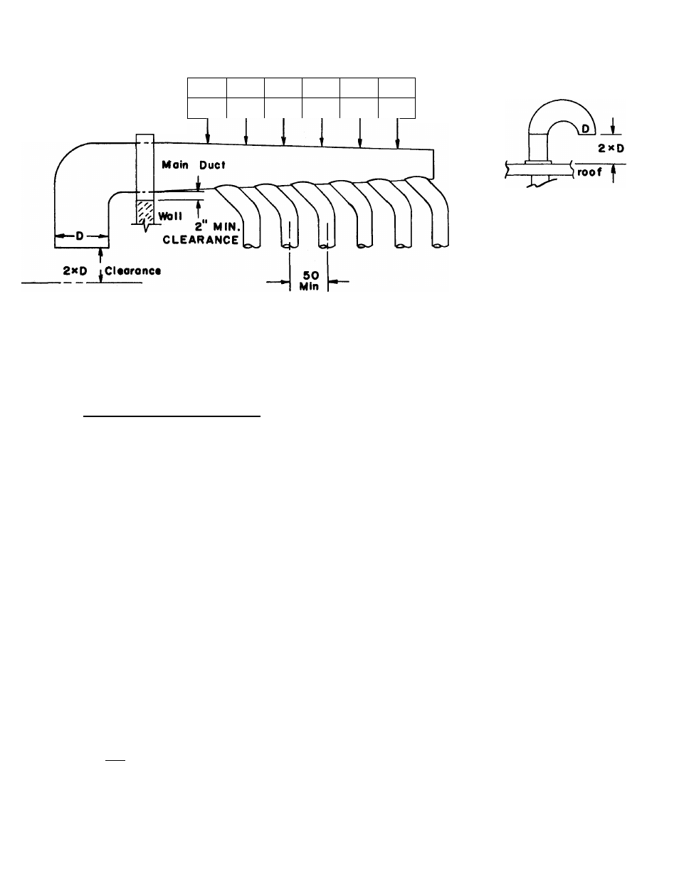
EXHAUST DUCT AND AIR INTAKE,
Where possible, it is desirable to provide
a separate exhaust air duct for each dryer. The duct should be 12" or 16"
diameter, depending upon the air outlet diameter of the dryer. The duct
should go as directly as possible to the outside air. Avoid right angle turns
in the ducting; use 30 degree or 45 degree angles Instead. The radius of the
elbows should preferably be 1 1/2 times the diameter of the duct. To protect
the outside end of the duct from the weather, it may be bent downward as indicated
in Figure 1. Leave at least twice the diameter of the duct clear between the duct
opening and the nearest obstruction. If the exhaust duct goes through the roof,
it may be protected from the weather by a hood, or by using a 180 degree turn to
point the opening down as indicated in Figure 2. In either case, allow at least
twice the diameter of the duct as clearance from the nearest obstruction as in
dicated above.
Do not use screens or caps on the outside opening of the exhaust duct. The
ducting should be smooth inside, with no projections from sheet metal screws or
other obstructions which will collect lint. When adding ducts, the duct to be
added should overlap the duct that it is to be connected to. Provide inspection
10-2