Altec Lansing 1715C User Manual
Page 15
Attention! The text in this document has been recognized automatically. To view the original document, you can use the "Original mode".
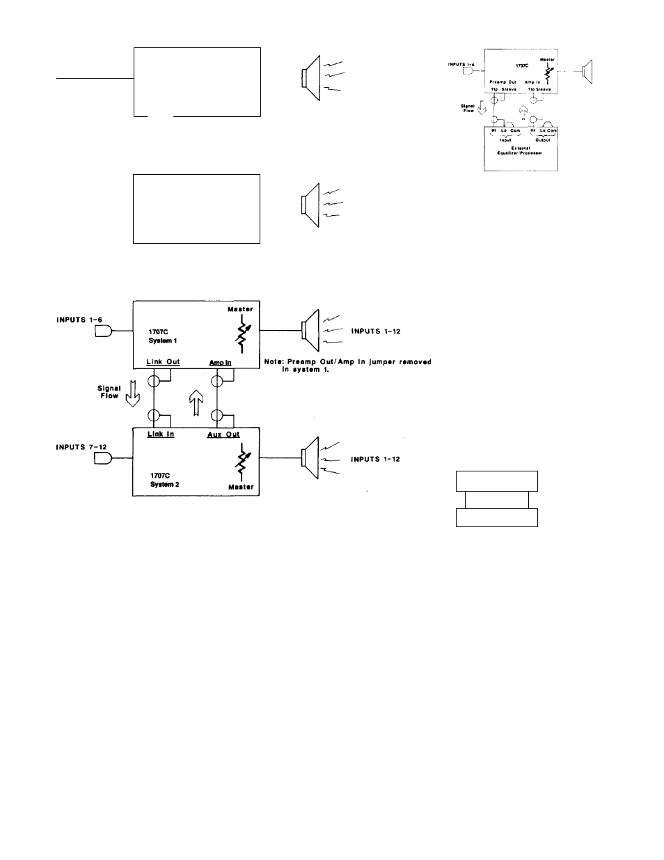
INPUTS 1-6
1
1---->
1707C
1__
)
f
System 1
Link Out
Zone 1 Master
Stgnii
flow
INPUTS 7-12
o
cP
Zone 1
(
inputs
1-e)
Link In
1707C
System 2
Zone 2 Master
.
Zone 2
.
(
inputs
1-12)
Figure 11. Typical Linking Connections
Figure 12. Patching an External Equalizer or
Other Signal Processing Device
AUX OUT Connections
The auxiliary output (AUX OUT) phono con
nector on the rear panel is wired directly
(internally) to the AMP IN phono connector.
You can use it to drive a second amplifier or a
tape recorder. Please refer to the
1707C/
1715C
mixer/power amplifier's block diagram
shown in Figure 7.
Battery Input Connections
You can power a system from the battery input
connector for auxiliary operation or standby
switchover. The battery input connector is the
three-terminal barrier strip located on the
upper-left rear panel of the mainframe. The
system requires two ±48V DC battery power
sources.
T
0
connect the battery backup system to the
three-terminal barrier strip, follow the three
steps shown in Figure 13.
O O
/ ; ?
(JB> 0 0 0 (i
!)
sup®
Rpmev* Citar Piatile Covar.
S1ap(*)
Cermaci DC Powor Seureaa
aa Shewn.
♦ COM
■=■
4« VOC
DC Power Sourcoa
Stop ®
Ro-lnalall Clear Plaatla
Proloetive Cover.
Figure 13. Battery Input Connections