Altec Lansing 1715C User Manual
Page 11
Attention! The text in this document has been recognized automatically. To view the original document, you can use the "Original mode".
ELECTRICAL CONNECTIONS FOR THE
1707C/1715C MIXER/POWER AMPLIFIERS
Power Connections (120 Volt, 50/60 Hz)
The mainframe configuration for both mixer/
power amplifiers comes with the power trans
former's primary line voltage strapped for
120-volt operation from the factory. Refer to
Table I for exact strapping details and other
voltage options.
The numbers in Table I correspond to the
numbered positions on the alternating cur
rent terminal block connector, which is ad
jacent to the power transformer. To select
a line voltage, install the colored primary
lead wires into the corresponding numbered
positions on the terminal block.
Table II. AC Fuse Selection Chart
Table I. AC Line Votage Selection and Strapping Chart
AC Line
Voltage
AC Line Fuse
100V
1707C
3.5 A/250 V
1715C
7.0 A/250 V
120 V
3.5 A/250 V
7.0 A/250 V
200V
2.0 A/250 V
4.0 A/250 V
220V
2.0 A/250 V
4.0 A/250 V
240 V
2.0 A/250 V
4.0 A/250 V
Primary
Line
Transformer Primary Lead Color
Voltage
WHITE
YELLOW
RED
BLUE
ORANGE
100 V
5
2
11
9
3
120 V
2
5
11
3
9
200V
5
2
7
10
8
220V
5
2
7
8
10
240V
2
5
7
8
10
---------------------------- NOTE------------------------------
Use of fuses other than those listed in
Table II will VOID THE WARRANTY.
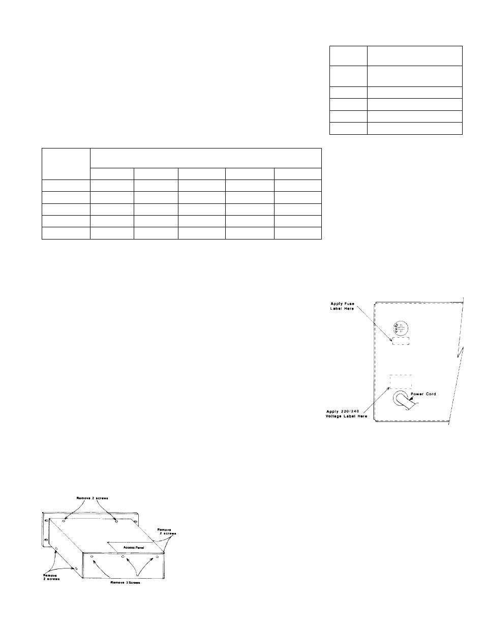
6. If you connected the power transformer’s
primary leads for 200—, 220—, or 240—volf
operation, perform steps 7,8, and 9 below
to prevent future confusion and possible
damage fo the amplifier. Otherwise, pro
ceed with step 10 below.
7. Affix the supplied 220/240 VAC label above
the power cord and cover the 120 VAC
silkscreened designation.
------------------------- NOTE---------------------------
Make sure the line voltage corresponds
with the selected line voltage power
rating BEFORE you connect the main
frame to the alternating current line.
Power Connections (100, 200, 220, or 240
Volt; 50/60 Hz)
You may change the mixer/power amplifier's
120-volt power connection to a 100—, 200—,
220—, or 240—volt power connection by re
strapping the power transformer’s primary
line voltage. Use the following procedure to
change the factory strapping to another line
voltage.
1. If you connected the mixer/power amplifier
to an alternating current power source,
disconnect it.
2. Remove and save the nine screws that
secure the mixer/power amplifier's top
cover. There are two screws near the
bottom of each side, two screws on top
near the rear edge of the front panel, and
three screws at the top edge of the rear
panel. Refer to Figure 1 for details.
Locate the voltage selection terminal
block between the side of the chassis and
the power transformer. Refer to Figure 2
for details.
8
.
w
>
o 2
o ni
^ X-
r.
Figure 2. Location of Voltage Selection
Terminal Block
While referring to Table I, disconnect the
primary lead wires from the terminal block.
Pull each wire firmly to disengage the push-
on connector. Then reconnect each lead
wire into its designated position on the
terminal block that corresponds to the de
sired line voltage. Press each connector
to snap into place.
Install the appropriate fuse value from
Table II.
Affix the 2-amp fuse/1707C, (4-amp/
1715C) label over the original 3.5 amp/
1707C, (7-amp/1715C silkscreened des
ignation. Refer to Figure 3 for where to
place the fuse label.
Figure 3. Application of International Stickers
9. Replace the standard AC line fuse with the
2-amp fuse/1707C,
(4-amp/1715C)
supplied. You should find the labels and
the fuse enclosed in the plastic bag with
this manual. Refer to Table II for an AC
fuse selection chart.
10. If you are not installing additional modules
in the mainframe right now, reinstall and
secure the top cover with the nine screws
previously removed in step 2 above.
-------------------------NOTE---------------------------
You can buy and install additional mod
ules into the mixer/power amplifier,
which has six ports that you can con
figure as input or output modules.
Figure 1. Top-Cover Removal