Altec Lansing 1715C User Manual
Page 13
Attention! The text in this document has been recognized automatically. To view the original document, you can use the "Original mode".
CONFIGURING THE MAINFRAME
The Mainframe’s Inner Workings
MODULE OUT NOMINAL’
/
100mV RMS ___
'
'
Z IN = 10K
PEAK
Note: Switches
not included
with mainframe
/77
USER INSTALLED STRAPS
*48V DC INPUT
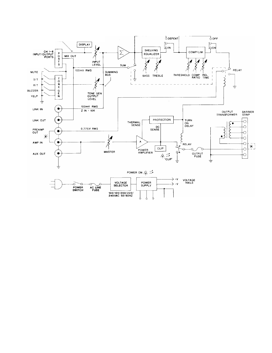
Figure 7. Block Diagram of 1707C/1715C
Mixer/Power Amplifiers
Figure 7 above displays a block diagram of
the mixer/power amplifier mainframe. Study
it carefully. To use the system's full capabil
ities, you'll need a good understanding of the
inner workings of the mainframe. Brief ex
planations of how the inside of the mainframe
works follow in the text below.
The signal coming from each additional input
module(likethe1781A, 1781AT, 1780A, or
1780AT) is simultaneously routed to the
mixer/power amplifier's front-panel nominal/
peak LED indicators and to the input channel
level controls. The dual LED nominal/peak
displays are pre-fader and designed to monitor
the output level from the corresponding
input module. The nominal (green) LED in
dicators have an approximate 10 dB window
over which they will illuminate. This makes
it easy to properly adjust the gain for each
input module while efficiently using the rest
of the system in terms of performance and
headroom.
The mixer/power amplifier then sums the
signal at the wiper of each input channel
level control into a true virtual ground sum
ming node or bus. The summing amplifier
has eight input channels — input channels
one through six on the front panel, tone gen
erator output, and the link input or LINK IN
on the rear panel. The summing amplifier's
output signal drives the link output, or LINK
OUT, located on the rear panel of the main
frame. The E.Q. and compressor/limiter sec
tions are in series with each other, as shown
in Figure 7. The compressor/limiter s output
signal drives the preamplifier output, or
PREAMP OUT, located on the rear panel
which then provides the input signal to the
main amplifier section.
The BASS and TREBLE E.Q. controls are
ideally suited to make adjustments to the
overall response of the mix. The low and high
frequency shelving equalizers provide *12
dB of boost and cut with the maximum boost
occurring at 100 Hz and 10kHz, respectively.
The
compressor/limiter
section
features
variable release time, compression ratio, and
threshold. The circuit uses a feed-forward
topology that will minimize level differences for
a more nearly constant output level. The
compression ratio can approach =>o:1, and the
attack time is fixed at approximately 10 ms.
The main amplifier section protects itself and
the load against radio frequency interference,
spurious oscillatory waveforms, excessive
temperatures, direct current, turn-on/turn-off
transients, and excess voltage/current phase
shift due to reactive loading.
A signal overload circuit monitors the level at
the output stage of the amplifier section. The
front-panel CLIP LED indicator illuminates
7