Altec Lansing 1715C User Manual
Page 12
Attention! The text in this document has been recognized automatically. To view the original document, you can use the "Original mode".
INSTALLING MODULES IN THE
MAINFRAME
For detailed instructions on how to install ad
ditional input and output modules, you may
order the following operating instruction
manuals from our Order Entry Department:
P/N 42-02-027720 for the 1781A/AT
Mic/Line Input Modules
P/N 42-02-026653 tor the 1780A/AT
Mic/Line Input Modules
P/N 42-02-027721 for the 1783 Line
Out put Module.
1. Remove and save the two screws that
secure the access panel to the top cover.
Refer to figure 1 for details.
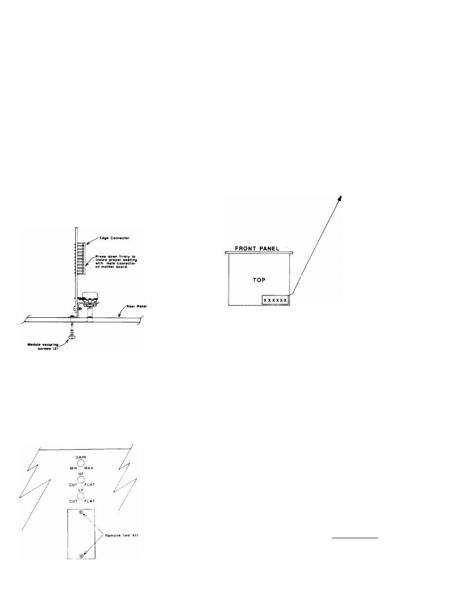
2. Plug the input or output module into one
of the six channel positions with the con
trols facing the rear as shown in Figure 4.
Secure the module with the two screws
provided.
Figure A. Module Installation
3. Remove the blank cover panel as shown
in Figure 5. Install the selected connector
assembly with the screws provided. Plug
the pigtail connector (from the main con
nector assembly) onto its appropriate male
mating connector on the module’s printed
circuit board.
On the top cover is a System Configuration
Label. Use it to indicate the module type,
configuration, and any options for future
reference. Write directly on the label with
a permanent marker. Refer to Figure 6 for
a display of this sample label.
------------------------- NOTE---------------------------
You may buy connector assemblies to
use for installing additional input/output
modules from ALTEC LANSING.
INPUT
OUTPUT
NONE
MUTE SLAVE
PRIORITY
XFORMER
RVC
♦ 4 dBm
INPUT
OUTPUT
NONE
MUTE SLAVE
PRIORITY
XFORMER
RVC
7
OdBm
INPUT
OUTPUT
NONE
MUTE SLAVE
PRIORITY
XFORMER
RVC
7
INPUT
OUTPUT
NONE
MUTE SLAVE
PRORITY
XFORMER
RVC
[Tf
И
Phantom
Pwr
INPUT
OUTPUT
NONE
MUTE SLAVE
РРЮР1ТТ
XFORMER
RVC
1
INPUT
OUTPUT
NONE
MUTE SLAVE
РРЮР1ТУ
XFORMER
RVC
Figure 6. System Configuration Labei
Figure 5. Removal of Blank Cover Panel
SHELF OR RACK MOUNTING THE 1707С/
1715C MIXER/POWER AMPLIFIERS
You may shelf mount or rack mount the main
frame. For shelf or countertop applications,
four rubber feet on the bottom of the chassis
will protect resting surfaces and provide
elevation for air flow underneath the unit. For
rack or cabinet applications, remove the four
rubber feet from the bottom of the chassis.
Then install the unit in the rack with the screws
and shoulder washers provided. The unit
must
have 1.75" of blank space both above and
below it.
Ventiliation
The mixer/power amplifier generates minimal
heat during normal use. Although the amount
of generated heat is low, make sure the main
frame is properly ventilated to prevent an ex
cessive temperature rise. Because the output
power devices (transistors) are sensitive to
heat, you should not place the amplifier be
tween other heat generating equipment or
in areas where the ambient temperature ex
ceeds 50°C (122°F).
If you mount the mainframe in an equipment
rack or cabinet with other heat producing
equipment, provide adequate space between
the units. Otherwise, the equipment may
become too warm.
If a rack or cabinet contains several amplifiers,
you may need to check the ambient air
temperature. To determine the ambient air
temperature, operate the system until the
temperature stabilizes. Measure the ambient
air with a bulb-type thermometer held at the
bottom of the uppermost amplifier.
-CAUTION-
Don’t let the thermometer bulb touch
the metal chassis. The chassis might
be hotter than the ambient air.
CAUTION-
If the air temperature exceeds 60°C
(140°F), place the equipment farther
apart or install a blower to provide
air movement within the cabinet.
Make sure you don't block the air-
intake holes located on the bottom of
the chassis or the exhaust holes on
the top cover.