Troy-Bilt 12069-7HP User Manual
Page 50
Attention! The text in this document has been recognized automatically. To view the original document, you can use the "Original mode".
3. The belt tension is correct if the
front of the clutch roller is l/4"-to-
5/16" away from the face of the
upright bracket that holds the ad
justment block in place (Photo
5-12). To measure this distance:
a) Without moving the clutch
roller, try inserting the 1/4”-
thick, slotted end of the belt ad
justment tool in between the
roller and the upright bracket.
(The flat edge of the tool must
be facing the roller.) Refer to
Photo 5-13.
b) If only the slotted portion of the
tool will fit, the belt tension is
correct as is.
c) If the slotted part of the tool will
not fit in, the belt is too loose.
d) If the full thickness (5/16") of
the tool easily fits in, the belt is
too tight.
4. If the belt tension is correct,
move the Wheels/Tines/PTO Drive
Lever back to NEUTRAL.
K
t
Sî-.
Ilf
Photo 5-13: Insert slotted end of
belt adjustment tool between roller
and bracket, with the flat side of the
slotted end facing the rolier.
How to Adjust Belt Tension:
1. You adjust the drive belt tension
by loosening the bolt securing the
belt adjustment block, then moving
the block up or down. Moving it
down will tighten the belt; moving
it up loosens the belt. (Hint: the
distance the block moves approxi
mately equals the distance the
roller moves.) In most cases, the
clutch roller will not have been
very far out of position, so the ad
justment block will only need to be
moved slightly (up or down).
2. Move the Wheels/Tines/PTO
Drive Lever to NEUTRAL posi
tion. The clutch roller will come
to rest anywhere on the face of the
belt adjustment block, depending
upon drive belt length and current
belt tension adjustment.
3. Insert the belt adjustment tool
through the hole in the side of the
adjustment block, spacing the ends
of the tool equally on both sides
(see Photo 5-14). Rotate the tool
so the slotted end faces down.
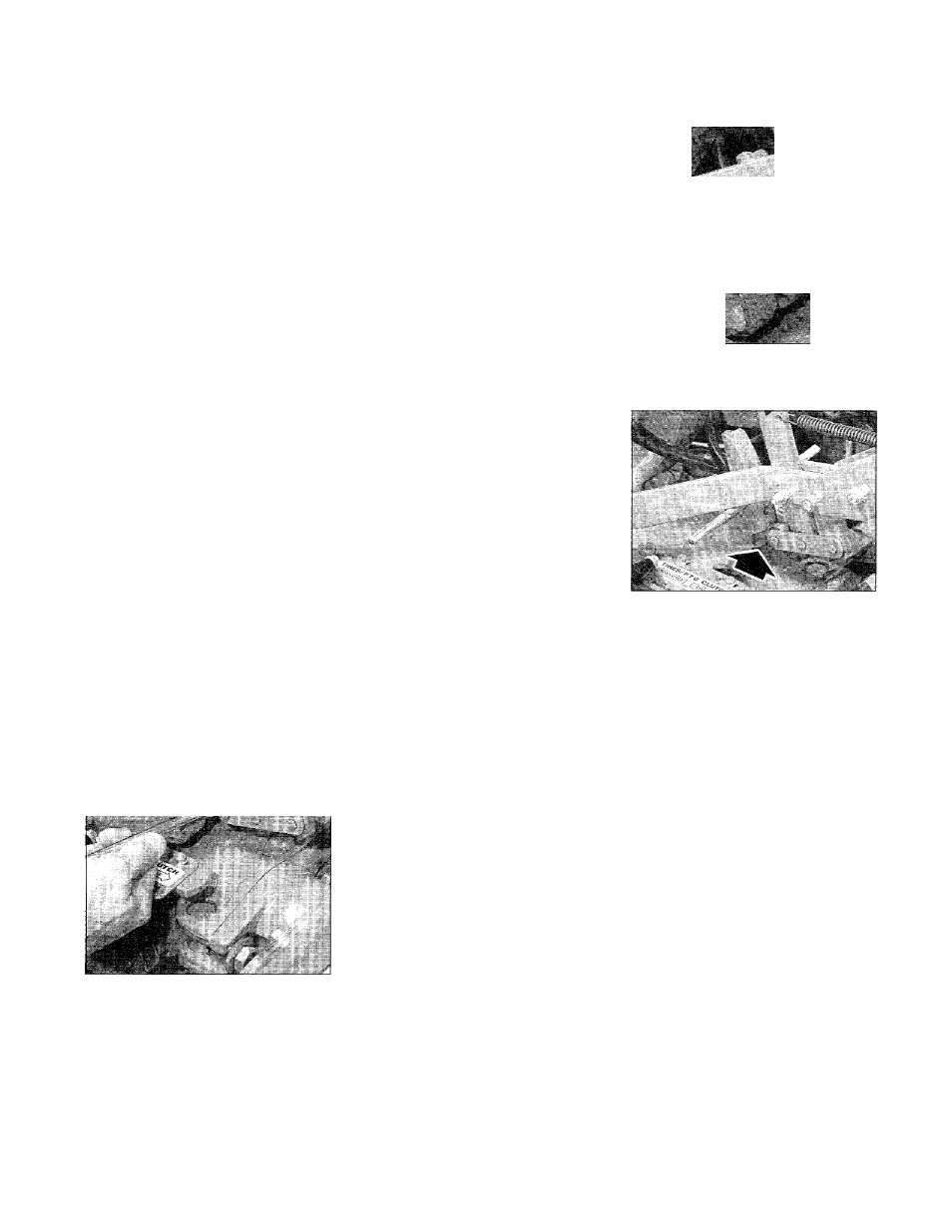
4. Place the Wheels/Tines/PTO
Drive Lever in FORWARD posi
tion. The arms of the clutch con
trol yoke will be resting on the belt
adjustment tool and the clutch
roller should be engaged slightly
beneath the adjustment block (see
Photo 5-15).
5. Use one hand to hold the drive
lever in FORWARD while using a
9/16" wrench to loosen (don’t re
move) the bolt at the back of the
belt adjustment block (Photo 5-16).
The adjustment block should be
free to move either up or down.
6. Push the drive lever down if the
belt needs tightening. Or pull the
lever up if the belt needs to be
loosened. Hold the drive lever in
place and tighten the bolt in the ad
justment block firmly.
7. Let go of the drive lever and re
move the belt adjustment tool from
the hole in the adjustment block.
Ait-
.k-- '
'.y
Photo 5-14: With Wheeis/Tines/PTO
Drive Lever in NEUTRAL, insert tool
through hole in adjustment biock.
Photo 5-15: With Drive Lever in
FORWARD position, dutch roller
should be engaged slightly beneath
the adjustment block.
sSir
ri' ■
Photo 5-16: Hold Drive Lever while
loosening bolt. Push lever down to
tighten belt; pull up to loosen belt.
8. Check the tension on the belt by
following the previous instructions
“How to Measure Belt Tension.”
Note: If the adjustment block is all
the way down and the measure
ment between the clutch roller and
the bracket is less than 1/4", then a
new drive belt is needed.
50