Step 3: remove tiller from shipping platform, Step 4: connect forward interlock wire harness, Warning – Troy-Bilt 12069-7HP User Manual
Page 12: Step 5: attach the wheels/tines/pto drive lever
Attention! The text in this document has been recognized automatically. To view the original document, you can use the "Original mode".
STEP 3: Remove Tiller from
Shipping Platform
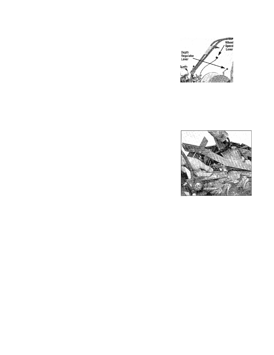
A. The Depth Regulator Lever
(Photo 2-6) may be secured to its
own mounting bracket with a plas
tic tie strap. Removing the tie
strap lets you move the Depth
Regulator Lever up or down. To
check, lift the hinged flap at the
end of the hood and look for a tie
strap around the lever. Use a scis
sors to cut it loose.
B. Move the Wheel Speed Lever
(Photo 2-6) to FREE WHEEL po
sition which lets the wheels turn
freely. FREEWHEEL
position is midway be
tween SLOW and
FAST positions. Then
lift the handlebars up
to clear the tines from
the platform. Pull the
handlebars firmly back
to roll the wheels out
of the platform wheel
wells.
C. Roll the tiller to a
level area where you
can complete the as
sembly steps.
Photo 2-6. Move tiller off shipping platform. Move
Wheel Speed Lever up or down to take wheels out
of gear.
STEP 4: Connect Forward
Interlock Wire Harness
A. Connect the plug on the wire
harness that leads from the lower
ends of the handlebars into the
wire harness receptacle on the top,
right side of the transmission
(Photo 2-7). This connection com
pletes the wiring circuit for the
Forward Interlock Safety System.
It must be connected or the engine
will not start.
B. Before connecting the plug, be
sure that it and the receptacle it’s
going into are clean.
^ WARNING
To avoid personal injury, test
the Forward Interlock Safety
System prior to each use of
the tiller to be sure it is func
tioning properly. See Section
4 in this Manual for the test
ing procedure to use.
Photo 2-7. Connect forward inter
lock wire harness plug to receptacle.
STEP 5: Attach the Wheels/Tines/PTO Drive Lever
This control lever is shown in Photo 2-1. To attach
it, you’ll need the clutch pawl spring (see Photo 2-2).
Tools required: one 3/4” and two 1/2" wrenches.
A. Loosen the large bolt at the top
of the handlebar base (Photo 2-8)
with a 3/4" wrench. Don’t remove
it. Swing the handlebars out of the
way to the right side of the tiller.
'■t ik
Photo 2-8. Loosen the large bolt
securing the handlebar base.
Swing handiebars to right side.
B. With two 1/2" wrenches, re
move and save the nut, star washer,
bushing and bolt from the hole at
the rear of the clutch yoke assem
bly plates (see Fig. 2-9, items A,
B, C, D).
C. Using two 1/2" wrenches, re
move (and save) the nut, star
washer and bolt (items E, F, and G,
Figure 2-9) attaching the short ver
tical link to the center of the yoke.
Keep the short link (with a bushing
inside it) upright after the bolt
comes out. If it swings down,
reposition it upright again.
D. Slide the plates located at the
end of the PTO drive lever over the
yoke and align the upper hole in
the plates with the hole at the rear
of the yoke (refer to Photo 2-10).
Insert the bushing (C, Figure 2-9)
inside the yoke and install the bolt
through the lever’s plates, bushing
and yoke. (Tap the bolt if neces
sary.) Add the star washer and nut
and tighten the nut finger-tight.
12