Very important i, Removing and replacing the tine attachment, Caution – Troy-Bilt 12069-7HP User Manual
Page 40: To remove tine attachment, The pto power unit
Attention! The text in this document has been recognized automatically. To view the original document, you can use the "Original mode".
THE PTO POWER UNIT
As explained on Page 2 of this
Manual, your tiller is really a self-
contained PTO power unit that was
shipped to you with a tine attach
ment connected to it. The tine at
tachment is quickly removed and
replaced by other attachments that
are available from us. The instruc
tions given here will familiarize
you with your PTO Power Unit.
Please read these pages carefully.
VERY IMPORTANT
I
Before operating your PTO Power
Unit for the first time, make sure
that you have:
• Read all the safety instructions
in Section 1 of this Manual and in
the Manual supplied with any at
tachment.
• Read the controls information
and operating procedures for the
tiller and engine described in
Sections 3 and 4 of this Owner/
Operator Manual.
• Read and understand the assem
bly instructions, controls informa
tion, and operating procedures for
the attachment as described in the
Owner/Operator Manual that is
supplied with the attachment.
Removing And Replacing The Tine Attachment
The following steps explain
how to remove and replace the tine
attachment. The only tool you will
need is a 3/4" wrench (minimum
12" long for good leverage).
There are two optional acces
sories that make the following
steps easier. The Kickstand acces
sory prevents the PTO Power Unit
(engine end) from falling forward
CAUTION
TO AVOID PERSONAL INJURY
OR DAMAGE TO EQUIPMENT:
• Stop the engine, remove
the electric start key, discon
nect the spark plug wire and
let the engine and muffler
cool before removing or in
stalling any attachment.
• Do not place hands, tools,
or any object near or inside
the PTO access hole when
the engine is running.
• When removing or replac
ing the tine attachment, be
careful of the sharp edges on
the tiller hood. Wear thick
gloves for hand protection.
• When the tine attachment is
removed, always place it in
the Tine Cradle or prop it up
to prevent the attachment
from falling forward.
¥;■
when an attachment is removed
(Photo 4-37). The Tine Attach
ment Cradle accessory gives you a
handy support in which to rest the
tine attachment when it is removed
from the tiller (see Photo 4-38).
For more information about other
accessories, refer to “Accessories”
at the back of this Manual.
>'■
■
iT
Photo 4-37: The Kickstand acces
sory prevents engine from tipping.
r ;
■'S-' !
\
Photo 4-38: The Tine Attachment
Cradie accessory is a handy option.
To Remove Tine Attachment;
1.
First be sure the engine is
stopped, the electric start key is re
moved, and the spark plug wire is
disconnected.
2. Place tiller on level ground.
3. Place the Wheels/Tines/PTO
Drive Lever in NEUTRAL (refer to
Photo 4-39).
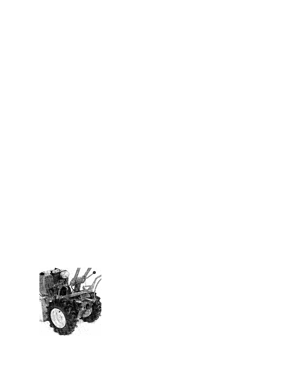
Photo 4-36: The PTO Power Unit with the tine attachment removed.
40