Step 2: attach the handlebars – Troy-Bilt 12069-7HP User Manual
Page 11
Attention! The text in this document has been recognized automatically. To view the original document, you can use the "Original mode".
STEP 2: Attach the Handlebars
Do not move tiller off shipping
platform unless handlebars are at
tached. This makes moving the
tiller easier and more controllable.
All the parts shown in Figure 2-4
(except the handlebars) are shipped
assembled. You must disassemble
these parts in order to attach the
handlebars.
A. Unwind the Handlebar Height
Adjustment Lever (Figure 2-4)
counterclockwise. Be prepared to
catch the nut, left clamp and left
ratchet as you remove the lever.
Completely withdraw the lever,
taking with it the right clamp and
right ratchet. Keep mating clamps
and ratchets grouped together.
B.
Place the handlebar ends on ei
ther side of the handlebar base and
the wire harness at the bottom of
the handlebars at the rear of the
base (Fig. 2-4).
C. Hold the right-side ratchet and
right-side clamp in position next to
right handlebar arm. Insert adjust
ment lever through the clamp, han
dlebar, ratchet and the base. Let
the adjustment lever protrude from
the other side of the base.
Note: The lever should pass freely
through the holes in the handlebar
ends. If it won’t- do not force it.
The wires to the Forward Interlock
Safety System may be blocking the
lever. Push a pencil through the
holes to gently move the wires
aside.
D.
Position the left-side ratchet
and left-side clamp next to the left
handlebar arm (see Fig. 2-4). Move
the adjustment lever all the way
through these parts. Hold the nut
in place and screw the lever into it.
Don’t fully tighten the lever yet.
E. Raise the handlebars (jiggling
them on the ratchets helps) to one
of two pre-set height settings.
Then tighten the lever (Photo 2-5).
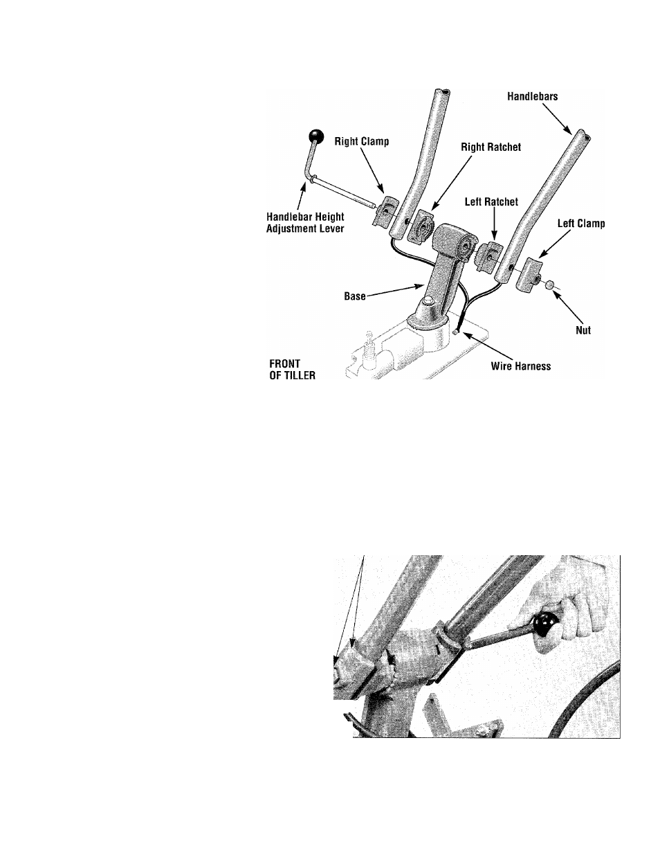
Figure 2-4. Unwind the Handiebar Height Adjustment Lever to separate the
handiebar assembiy parts. Keep the mating left-side ratchet and damp
grouped together, and the right-side ratchet and damp grouped. Place the
handlebars so the ends are on either side of the handlebar base. Reas
semble all parts securely.
Left Side
Clamp With
Nut
Photo 2-5. When handlebars are in position, reassemble all the compo
nents. Insert the Handlebar Adjustment Lever from right to ieft through ail
the parts. As shown above, securely tighten the iever.
11