Poulan 195 User Manual
Page 8
Attention! The text in this document has been recognized automatically. To view the original document, you can use the "Original mode".
f.
g
Insert the four shield screws one at a time
through the gear box and shield, then thread
them into retention plate
Tighten the screws evenly and securely with
the 3/16” hex wrench (provided).
Install the dust cup over the arbor shaft.
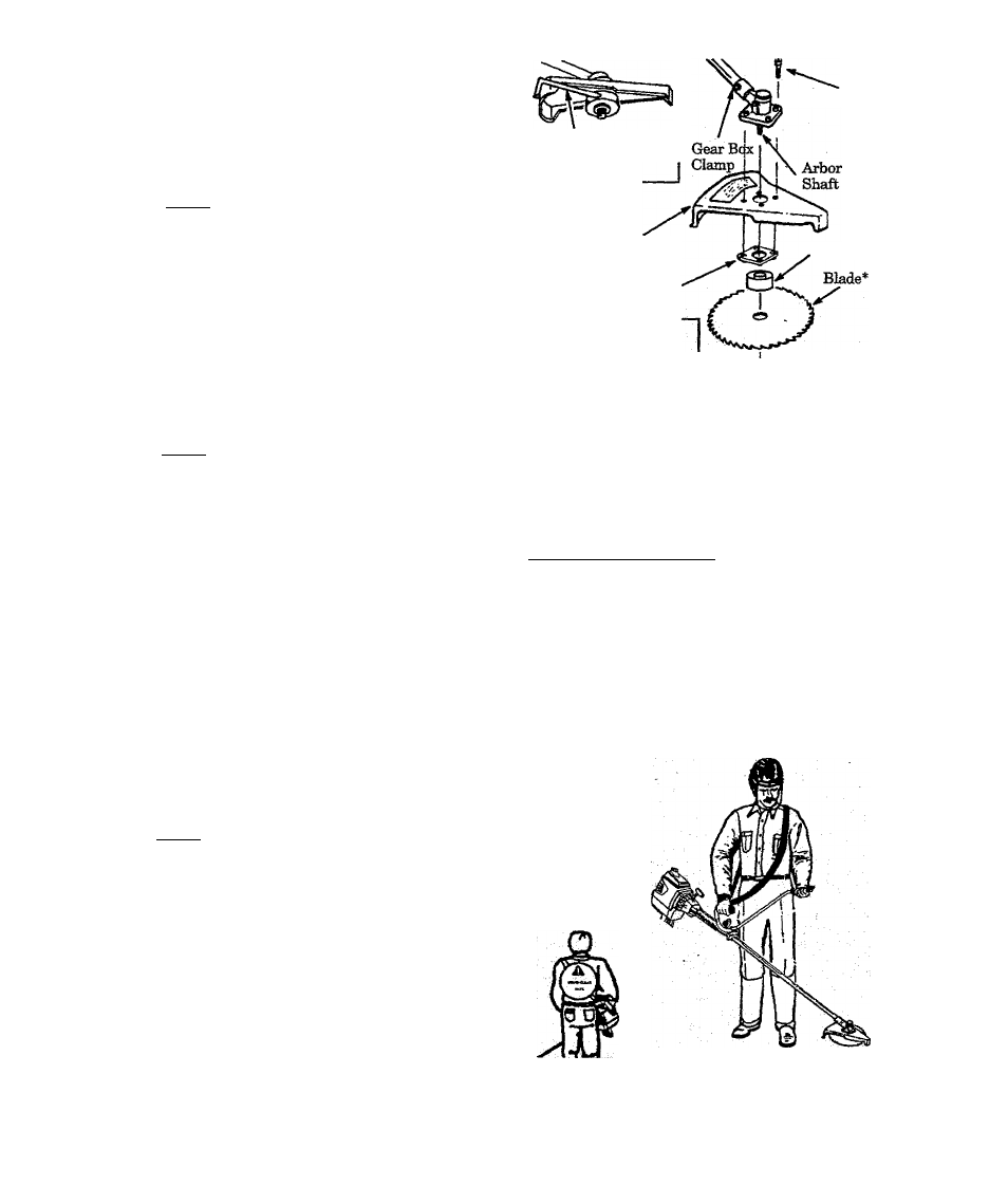
h. Install blade over arbor shaft, making sure the
hole in the center of the blade is fitted around
. the raised center on the dust cup. Figure 6 .
NOTE: When installing blade, make sure teeth
on blade are oriented as shown in Figure 6 .
i.
Install the large flat washer “G.”, cupped
washer “H.”, and nut "E.” as shown in Rg-
ure 6. Be sure cupped washer "H.” is install^
as shown in Figure 6 (inset).
Align hole in the dust cup with the hole in the
side of the gear box by turning the dust cup.
Insert the large hex wrench (provided) into the
aligned holes. Figure 6 (inset, upper left).
While holding the hex wrench in position,
firmly tighten nut "E,” counterdockv^e with
a Tvrench.
m. Remove tfm hex wrench.
n. Turn blade by hand. Ifthe blade binds against
shield, blade is not centered. Heinstall blade.
NOTE: To remove the blade, align holes as in
step “j.”; then, insert the large hex wrendi.
Unthread hex flange nut and remove parts. Be
sure to store the blade, flat washer, cupped
“wmshm^^andheXflang^iuftTbrTutm^
J-
k.
l.
Hex Wrench in
aligned holes
Screw C.*
Widest Portion
of Shield*
Toward Engine
Cupped Side
Toward i Washer H.*'
Blade j ^
Dust Cup
Retention
Plate J.*
1 ^Washer G.*
Washer H.*
(see inset)
— Nut E.*
Figure 6
A
warntotg
_
Paita-iiotedwilir*~ar€rcrfti^ai"^'d
misst
ne
sup
plied by your POUtiAN PRO dealer. Failure to
use proper parts can cause the blade to fly off
and seriously hurt you or others.
6. SHOimOER STRAP
A WARNING
Proper
shoxilder
strap
and
handlebar
adjust
ments
before
starting
the
engine
are
required
for safe and efficient use.
a. Tiy on shoulder strap and adjust for fit and
balance before startii^ the engine and begin
ning a cutting operation.
b. Insert your rigiit arm and head through the
shoulder strap and allow it to rest on your left
shoulder. Make sure the danger sign is on your
back and the hook is to the right side of your
waist. Figure 7.
NOTE: A one—half twist is built in the shoulder
strap to allow the strap to rest fiat on the Moulder.
c. Adjust the strap so that the hook will be about
10 inches below the waist when the hook is at
tached to the shoulder strap.
d. Fasten shoulder strap hook to damp and lift
tool to the operating position. Figure 7.
e. Check for the following:
1
.
2
.
3,
4.
5.
6,
7,
Left arm extended, hand holding handlebar
grip-
Eight hand holding trigger handle, fingers on
throttle trigger.
Engine below waist level.
Shoulder strap pad centered on left shoulder.
Danger sign centered on your back.
Full weight of tool on left shoxdder.
Without operator bending over, the blade or
trimmer head is near and parallel to the
ground and easily contacts material to he cut.
f. Modify these initial adjustments as necessary
for comfort and control but do not locate the
handlebar mounting block below the point of
the arrow on the safefylabels. Do not locate the
shoulder strap damp in any position other
than
between the engine and handlebar
mounting block.
OPERATING
POSITION
Danger S%n
Centered on
Your Back
Figure 7
- 8 -