Notes – Poulan 195 User Manual
Page 21
Attention! The text in this document has been recognized automatically. To view the original document, you can use the "Original mode".
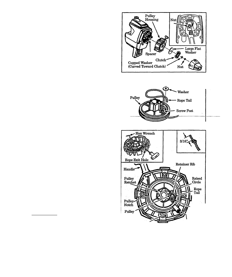
11. Remove the rope retainer screw. Figure 28, Re
move any remaining rope from around the pulley
ratchet. Figure 29.
12. Hold риДеу housing as shown in Figure 29 (in
set), Hand turn pulli^ clockwise as far as it will go.
13. Turn pulley counterclockwise until the pulley
notch is aligned with the housing notch next to the
pull^ tab and screw. Figure 29 .
14. Next, turn the puUqy one complete turn counter
clockwise until the notches are aligned again.
15,Insert the hex wrench into the hole formed by the
notches to hold the pulley in position. Fig
ure 29 (inset—upper left).
16. Use a 42” length of replacement rope.
17. Move away 10 feet (3 meters) from the fuel tank
with the replacement rope. Use a match and melt
both ends of the rope to prevent fireiying.
18. Pull melted ends through a thick, dean rag while
rope is still hot to obtain smooth, pointed ends.
lO.Insert one end of the rope throu^ the handle and
secш«-with-aJшot.JLíeave^a.ЗД6!lpigtailheЬшd_
the knot. Figure 29 (inset—upper right),
20.1nsert other end of the rope throu^ the rope exit
hole into the inside of the housing, into the puhey
and up through the pull^ hole. Figure 29.
21. Wrap the rope counterdockwise around the
pulley ratchet and tuck loose end under the rope
at the pull^ hole. Figures 28 & 29 . Leave a 1
inch tail laying flat on top of the pull^ between the
retainer rib and the retainer post. Figure 29 .
The rope tail must not extend beyond the raised
drde on the pulley to prevent interference with
thepuU^tab, Figure29.
22. Thread rope retainer screw into the screw post.
Figure 29. Do not overt^hten siaow.
23. HoId the rope taut at the rope exit hole so the
puH^wifl not move. Remove hex wrench. Allow
rope to rewind sb)ii»Zy.
24. Make sure spacer is in place. See Figure 27. Re
verse steps 1 throu^ 10 to re—assemble.
I CAUnON;
I
When reinstaUing the clutch^
ti^ten the nut until the cupped washer is
flattened against the clutch. Over or under
tighteningnut can cause engine damage.
Figure 27
Rope
Retainer Screw
Figure 28
Hole
Housing Notch
Rope
Retainer
Screw/Post
PuIl^Tab
and Screw
Figure 29
NOTES
- 2 1 -