E, 8т!^штеккоре – Poulan 195 User Manual
Page 20
Attention! The text in this document has been recognized automatically. To view the original document, you can use the "Original mode".
d, DECELERATION CHECK
1. Allow en^e to idle, then squeeze throttle
trigger fully.
2. Allow engine to run at full speed for about 1
second,
3.
Releasethethrottietriggertotheidleposi-
tion and listen to the deceleration of the en-
gine. It must return to idle smoothly and
within 1 to 2 seconds.
a. If performance is satisfactory, pro
ceed to step “4.”
b. H the engine slowly or erratically
returns to idle or idles erratically^
repeat "‘Idle Speed Adjustment” or con
tinue throu^ Low Speed Mixture and
High Speed Mixture .^ustments to ob
tain proper deceleration.
4. Recheck idle speed.
e. I^W SPEED MIXTURE ADJUSTMENT
1. Allow engine to idle.
2. Turn the low speed mixture screw (Figure
25) slowly dockwise until the speed starts
to drop. Note this position.
3. Turn the low ^eed mixture screw counter-
dockwise until the speed increases and
then starts to drop again. Note this posi
tion.
------- '^T~Setthelow^6edTaixtai“fe screw at ihemod^
point between the two positions.
6,
Follow
instructions
in
“Acceleration
Check” and “Deceleration Check,”
£ HIGH SPEED MIXTURE ADJUSTMENT
I CAU^OND
D
o
not operate engine at full
throttle for prolonged periods while mak
ing high speed adjustments as damage to
the engine can occur.
1. Support the lower end so the trimmer line
is oil the ground and will not make contact
with any object.
2. Allow engine to idle, then squeeze throttle
trigger fully,
NOTE: Perform steps “3.” through “5,” at full
throttle.
3.
Turn high ^eed mixture screw C^-
ure 25) very slowly dockwise tmtil engine
speed is reduced.
4. Turn high speed mixture screw very slowly
counterclockwise. Stop when the engine
begins to run roughly.
5. Turn screw slowly the minimum amount
dockwise until the engine runs smoothly.
6.
Follow
instructions
in
“Acceleration
Check” and “Deceleration Check”,
CAUnoi^ If the engine does not operate ac
cording to these instructions after repeat
ing the adjusting steps, do not use the unit.
Take it to your Authorized Service Dealer.
High Speed
L
o
^ Speed Adjustment Screw
Idle speed
Adjustment
Screw
Air Filter
Cover
Figure 25
E, 8Т!^ШТЕККОРЕ
• Replace a starter rope that breaks.
A DANGER
Never start the enMne with the clutch shroud re
moved, The dutch will fly apart and cause serp-
ousit^fujy.
A WARNING
Dp not remove the retainii^ tab and screw or
thb
The spring beneath the pulley is un
der tension and can fly out and cause serious in
jury. If any part of pulley housing assembly is
damaged other than the ^pe, do not use unit.
ervice Dealer.
L
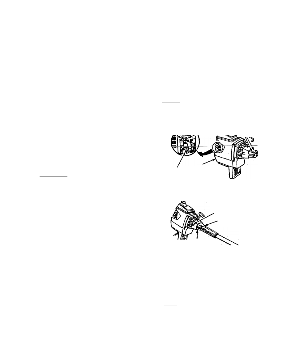
Figure 26.
2, Retuove the screw from the trigger housing, (refer
3, RemoT^ the trigger housing from the handlebar.
4, Carefully pull wire assembly out of the foam grip.
5, Loosen two “Nose Cone” screws and remove the
tiihP fix)m the dutch shroud. ^
6, Eeinove the four dutch shroud screws with the
&?n^
wrench provided. Figure 26 .
7, feparate dutch shroud from engine. Figure 26.
-
20
"
Spar]^
Plug
Wire
Clutch
Shroud Screws
“NoseCk)ne”
Screws
Clutch
Shroud
Figure 26
A DANGER
Use only a hand tool to remove the clutch. Do not
use any type of motorized unit or strike the
clutch in any way. Otherwise, the clutch wUl fly
apart and cause serious injury.
8. Hold the “Flats” of the dutch with an adjustable
wrendi. Figure 27 (inset). Remove the nut coun
terclockwise with a wrench.
NOTE: Clutch will slide off the crankshaft intact.
9. Remove the cupp^ washer, dutch, and large flat
washer as diown in Figure 27.
TO. ifomove pulley housing from engine. Figure 27.