Tiller off shippini platfim, Step 4: cinnect firwafil literlick wire hariess, Step 5: attaci wleels/fines/pto drive lever – Troy-Bilt 682J User Manual
Page 7
Attention! The text in this document has been recognized automatically. To view the original document, you can use the "Original mode".
Section 2: Assembif
lever and could be damaged. You may
gently move the wires aside if this
condition occurs.
4. Raise handlebars to one of two height
settings and tighten the height adjustment
lever. Also, make sure all other mounting
hardware is securely tightened.
Figure
2-3.
Fully
assembled
handle
bars.
NOTE: Fully assembled handlebar
assembly should appear as shown in
Figure 2-3.
STEP
3:
Move
Tiller Off Shippini
Platfim
1. Set the Depth Regulator Lever
(A, Figure 2-4) to Travel position. Do this
by lifting the tiller by the handlebars, then
pulling straight back on the lever and
sliding down to the highest notched
setting.
2.
Set the Wheel Speed Lever (B, Figure
2-4) to Freewheel position. To do this,
move the lever approximately halfway
between the Fast and Slow settings while
you rock the tiller forward and backward
until the wheels move freely.
3.
Lift Handlebars high enough to clear
tiller tines and pull back firmly to dislodge
the tiller from the platform wheel wells.
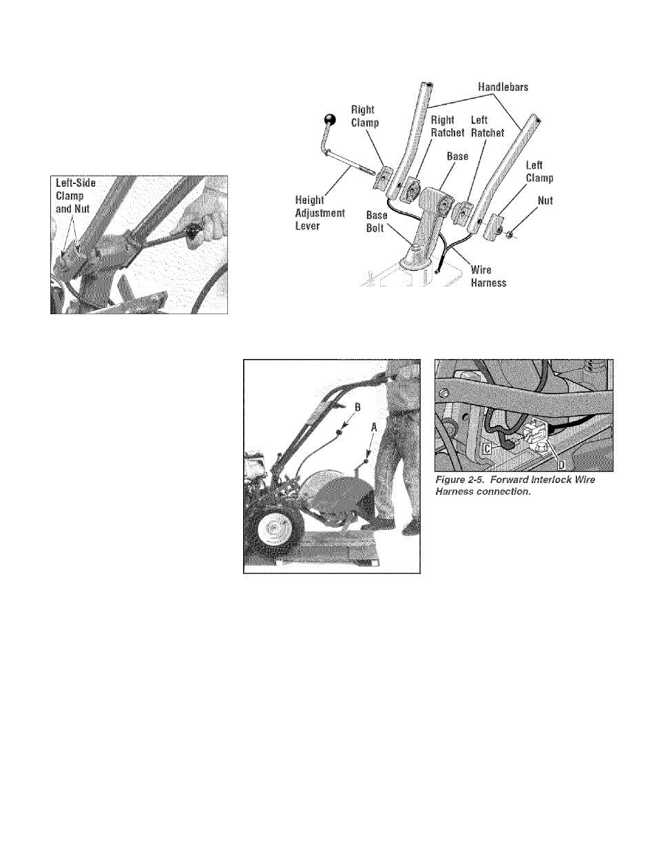
STEP 4: Cinnect Firwafil
literlick Wire Hariess
1. Remove any dirt from the Forward
Interlock wire harness plug (C, Figure
2-5) and its receptacle (D).
2. Connect the Forward Interlock wire
harness plug (C, Figure 2-5) to the recep
tacle (D).
STEP 5: AttacI
Wleels/fines/PTO Drive Lever
1. Loosen the bolt (Figure 2-2) on the
FRONT
■ ■
OF TILLER ..............
Figure 2-2. Handlebar assembly.
Figure 2-4: Photo shows the Depth
Regulator Lever (A) and the Wheel
Speed Lever (B).
handlebar base and swing the handlebars
out to the right side.
2.
Remove both sets of nuts, star
washers, screws, and one bushing
(A, B, C, D, E, F, G, Figure 2-6) from the
yoke plates (H). There is a bushing inside
the short link (I). Be careful not to lose it
when removing screw (G).
3.
Slide the plates at the end of the
Wheels/Tines/PTO Lever over the yoke
plates (Figure 2-9). To aid in the next
step, insert a screw temporarily into the
forward most holes (J, Figure 2-7) of the
yoke plates and the lever.
4.
Align the rear most holes of the yoke
plates and the Wheels/Tines/PTO Lever.
Use long nose pliers to hold the bushing
(L, Figure 27) in place while inserting the
screw (K) through the lever and yoke
plates. Install star washer (B, Figure 2-6)
and nut (A), then hand tighten.
5. Retrieve the clutch pawl spring (Figure
2
-
8
)
from hardware bag.