Controls – Ariens GARDEN TRACTORS 931013 S-14G User Manual
Page 4
Attention! The text in this document has been recognized automatically. To view the original document, you can use the "Original mode".
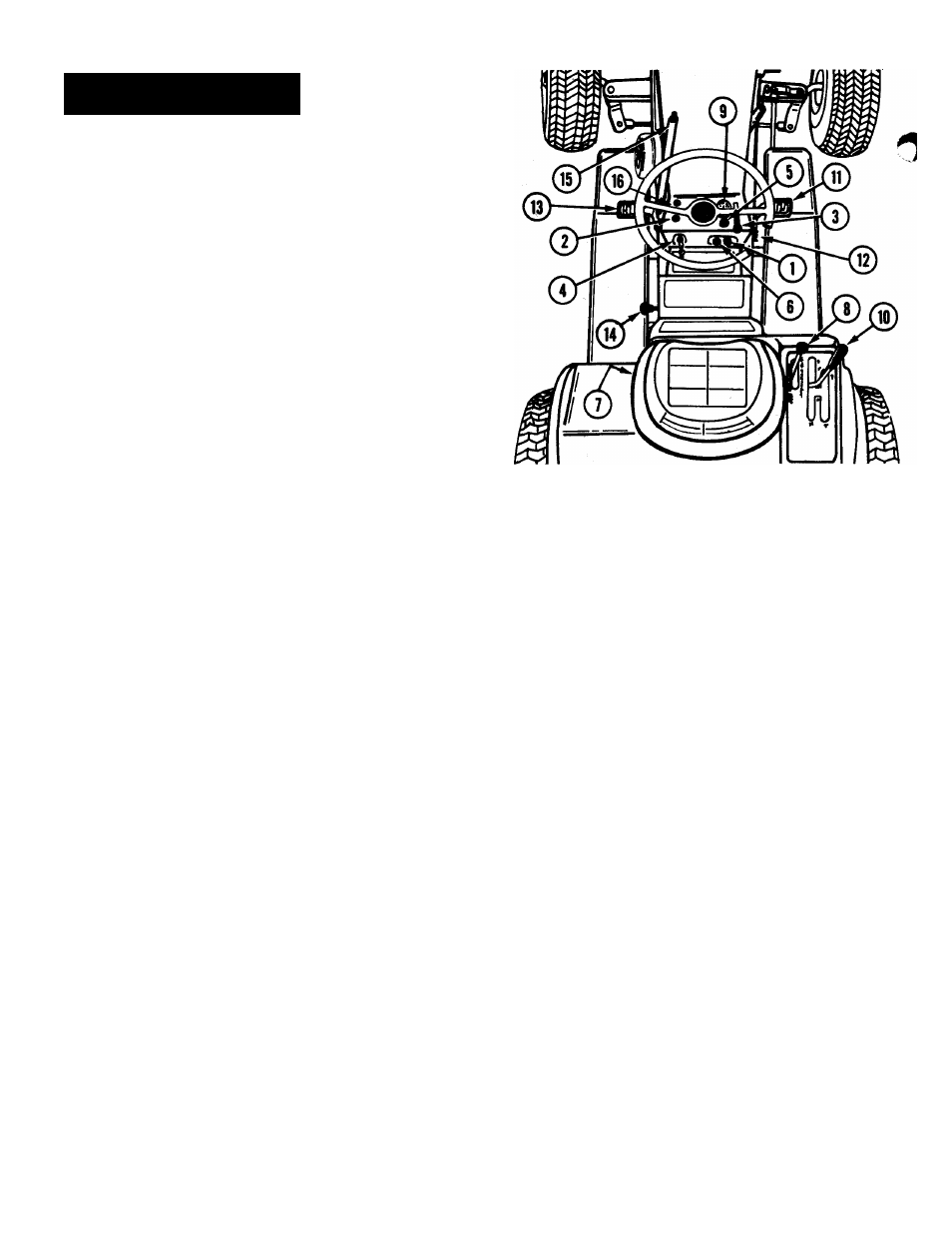
CONTROLS
Implement
Power
Control
Switch
(Figure
1).
Pull the switch out (ON) to engage the electro
magnetic clutch to drive the mower and front mount
ed attachments.
NOTE: This switchQ must be pushed in (OFF) to
disengage the drive before the engine will start or to
allow engine to keep running if the operator gets
off the seat.
Implement Power Indicator Light (Figure 1). This
light glows red when the implement power control
«witch (T) is pulled out to indicate that the mower
or front mounted attachment is engaged.
©
©
©
©
©
©
©
©
Throttle Lever (Figure 1). Raise the lever to in
crease engine speed. Lower the lever to decrease
engine speed.
Ignition Switch (Figure 1). Turn the key fully
clockwise to start the engine and release when the
engine starts. Turn the key counterclockwise to stop
the engine.
Choke Control (Figure 1). Pull choke control out
when attempting to start a cold engine or when
starting during cold weather. When engine starts,
gradually push choke in. Normally, it is not necessary
to use the choke when starting a warm engine.
Light Switch (Figure 1). Pull the switch out to
turn on the front and rear lights. The ignition key
must be turned on before the lights work.
Seat Safety Interlock Switch (Figure 1) This
switch, located in the seat, is closed by the operators
weight. If the operator leaves the seat for any
reason while the PTO is "ON" or the shift lever
is not in "NEUTRAL" the PTO clutch and engine
ignition are both shut off. When the PTO is "OFF"
and the shift lever is in "NEUTRAL" leaving the seat
will not cause the engine to stop.
Hydraulic Lift (Figure 1) Model S-14G only).
This lever controls the hydraulic system used to
raise and lower attachments. The lever has four
positions - UP, HOLD, DOWN and FLOAT. The
normal out-of-use position is the "HOLD" position,
whereby the attachment will not raise or lower. When
it is desired to raise the implement, move the lever
to the "UP" position, to lower the attachment move
the lever to the "DOWN" position. Place the lever
in the "FLOAT" position to allow the attachments
to follow the ground contours.
Ammeter (Figure)). The ammeter indicates the
rate of battery charge or discharge. The indicator
should register on the (-)-) side of the dial when the
engine is running at any speed above a slow idle.
When the engine is idling or with a fully charged
battery, the ammeter may not show charge. Should
the ammeter register on the (—) side of the dial for
an extended period of time with the engine running,
it indicates the alternator is not charging the battery.
Check the battery connections or contact your dealer.
©
®
®
®
®
FIGURE 1
Gear Shift Lever (Figure 1) This lever selects any
of four forward speeds or reverse.
NOTE: This lever must be placed in the NEUTRAL
position before engine will start
Brake Pedal (Figure 1) When this pedal is depressed
the friction brakes will be applied to stop the tractor,
DEPRESS THE CLUTCH PEDAL ® BEFORE AT
TEMPTING TO STOP THE TRACTOR WITH THE
WHEEL BRAKES.
Parking Brake (Figure 1) The parking brake is a
latch that locks the brake pedal. To apply the park
ing brake, depress the brake pedal, flip up the parking
brake latch.® To disengage the parking brake,
depress the brake pedal and push down the latch.
Clutch Pedal (Figure 1) Depressing this pedal re
moves the idler pulley from the drive belt and dis
connects the engine from the drive train. Depress the
clutch to shift gears or before attempting to stop.
Lift Selector - Connects the attachment lift to
front/center or rear rock shaft. See page 12 and
Figure 23 for operation.
Manual Lift Lever (Figure 1) (Model S-10G only).
To raise attachment, press the thumb release, pull lever
rearward and lock in the raised position. To lower
attachment, press the thumb release and move lever
forward. This lever is spring loaded to the rear position
when the manual lift assist springs are engaged.
Implement Reset Button - Press to restart PTO in
the event the operator leaves the seat momentarily.
Under these conditions the PTO and engine ignition
will be shut off. If the operator sits down before the
engine stops revolving, the engine will restart, but
the PTO will not start until the reset button ® is
pushed. If the engine stops, the normal starting
procedure
(Implement
switch
®OFF;
Shift
lever
® in NEUTRAL) must be followed.
-4