Ariens GARDEN TRACTORS 931013 S-14G User Manual
Page 10
Attention! The text in this document has been recognized automatically. To view the original document, you can use the "Original mode".
If the steering develops a wandering characteristic or if
excessive tire wear develops, the toe-in of the front wheels
should be checked. If the toe-in is incorrect, adjust as follows;
1. Loosen jam nuts A and B, Figure IB.
2.
Rotate tie-rod until toe-in is correct. Shorten tie-rod to
decrease toe-in. Lengthen it to increase toe-in.
3. Tighten jam nuts A and B after correct toe-in is obtained.
BRAKE ADJUSTMENT
The tractor brakes will require adjustment when the brake
pedal depresses over two inches. To adjust the brakes proceed
as follows:
1. Block up the rear of the tractor with the wheels off the
ground.
2. Remove the wheel lug nuts and remove the wheel.
3. Insert a screw driver in the slot in the brake drum (See
Figure 17)' and tighten the star washer until the brakes are
snug and the
drum
does not turn. Back off the star washer
one full turn.
4. Replace the wheel and secure with the wheel lug nuts.
Repeat adjustment on the opposite wheel.
STAR WASHER
FIGURE 17
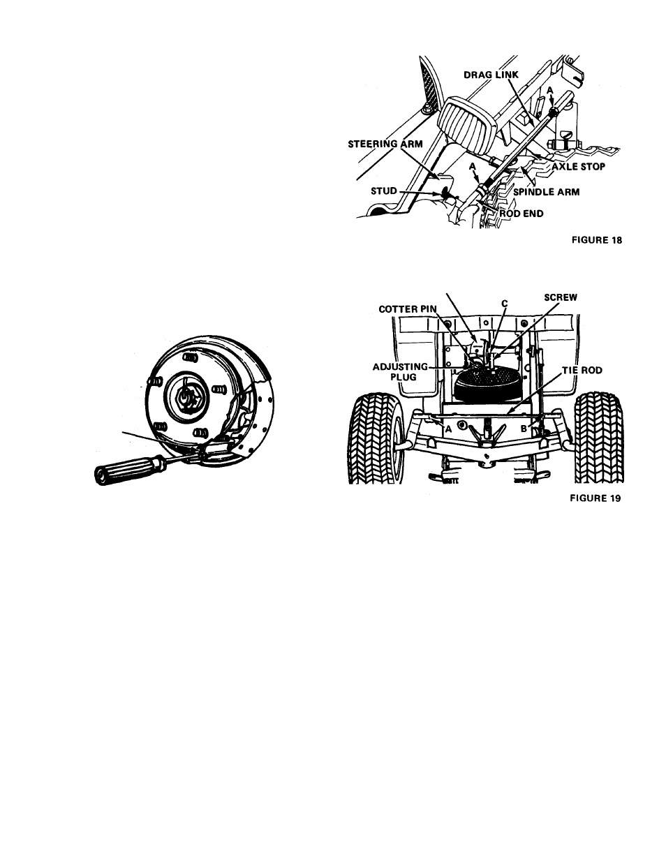
STEERING GEAR ADJUSTMENT
If loose play is noticed in the steering system after con
tinued use, the steering gear may require adjusting to remove
excessive backlash between the gears. Adjust steering gear
using the followirig procedure:
1. Raise front of tractor so that the tires clear the ground.
2. Remove cotter pin identified in Figure 19.
3.
Loosen jam nut C, Figure 19 and turn adjusting screw out
(counter-clockwise) IVi turns.
4. Tighten adjusting plug. Figure 19, to 10-14 ft. lbs. of
torque.
5. Rotate adjusting plug out slightly to align nearest slot in
the plug with the cotter pin hole and reinstall the cotter pin.
6. Hold jam nut and turn adjusting screw. Figure 19,
clockwise (in) until backlash is removed from steering wheel.
DO NOT FORCE ADJUSTING SCREW. Torque jam nuts
35-45 ft. lbs. while holding adjusting screw in position.
7.
Turn Steering wheel from lock to lock and check for
binding or dragging inside gearbox. If any binding or
dragging exists, it will be necessary to loosen the adjusting
screw and/or the adjusting plug slightly until steering wheel
turns freely with no loose play.
STEERING GEAR
CAM
FOLLOWER
ADJUSTING
STEERING STOP ADJUSTMENT
When making a full right hand turn, the spindle arm
should contact the axle stop as shown in Figure 18. When
making a full left hand turn, the left spindle arm should
contact the left axle stop. Proceed as follows to adjust the
steering stops.
1.
Rotate front wheels to the right until right spindle arm
contacts the axle stop. Figure 18.
2.
Remove drag link rod end from steering arm. Figure 18,
and loosen jam nuts A.
2a. Rotate steering wheel clockwise until steering gear
bottoms. Back off 1/8-1/4 turn counter clockwise.
3. Rotate drag link as required while preventing the loose rod
end from turning until the stud is approximately V: hole to
the rear of hole in steering arm, Figure 18. Be sure axle stop
contacts steering arm.
4. Reinstall rod end stud in steering arm and tighten jam
nuts A.
5. Rotate wheels completely to the left. The left spindle
arm should contact left axle stop. If it does not, repeat step j|
2 and shorten drag links slightly until both spindle arms con-
tact their respective axle stops when making full turns In '
either direction.
10-