Ariens GARDEN TRACTORS 931013 S-14G User Manual
Page 11
Attention! The text in this document has been recognized automatically. To view the original document, you can use the "Original mode".
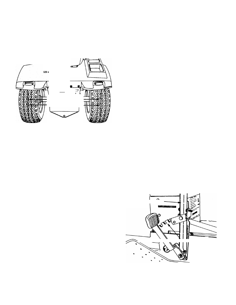
REAR WHEEL TREAD ADJUSTMENT
The rear wheels are normally assembled in the narrow
tread position, shown in Figure 20. The wheels can be turned
on the hubs for a wider tread. The wide tread provides greater
stability on hillsides and on rough terrain.
Remove the wheel lug nuts, turn the wheels around with
the valve stems inward and re-assemble on the hub.
NARROW WHEEL TREAD SETTING
10.50 X 12 TIRES SHOWN)
• *er
I A A l c
NARROW
23
X
10.50
X
12 = 32%
0 WIDE
23
X
10.50
X
12 = 35'/4
FIGURE 20
If Chevron tread tires are used, remove the wheel lug
nuts and re-assemble the wheels on opposite sides of the
tractor with the valve stems turned inward. Interchanging
the wheels is necessary to maintain proper direction of
rotation for traction tires.
MANUAL LIFT OPERATION
Manual Lift Lever {Figure 21) (Model S-10G only). To
raise attachment, depress thumb release and pull lever to the
rear until the locking pin engages in the proper quadrant
notch to obtain desired attachment height. To lower attach
ment, depress thumb release and push lever forward. After the
attachment touches the ground the force from the lift assist
springs will resist the forward motion of the lift lever. The
amount of resistance is relative to the spring adjustment.
The two springs shown in Figure 24 are used to provide
lift assist. The tension on these springs should be adjusted
using the chains shown in Figure 22, so the front mounted
attachments can be raised or lowered with the lift lever by
the operator.
A
CAUTION:
WHEN
ADJUSTING
CHAIN
TENSION
ALWA YS GRASP CHAIN HANDLE FIRML Y (NOT
THE CHAIN) AS CONSIDERABLE TENSION IS ON
THE
CHAIN
AND
INJURY
TO
THE
HANDS
COULD RESULT.
The' center rock shaft shown in Figure 24 is used to raise
and lower the rotary mower. This rock shaft is connected to
the manual lift lever through the link. The connection at the
rock shaft is made through the slotted hole which allows
the rock shaft to move up and down when in the lowered
position, allowing the mower to float without causing the lift
lever to move.
The center rock shaft pan flotation spring, shown in Figure
24 provides mower flotation. The tension on the spring can be
increased or decreased by presetting the latch bar to a dif
ferent notch when the pan is fully raised. The bottom notch
provides the greatest flotation.
The front/center or rear rock shaft is selected for operation
by the manual lift lever by the lift selector knob. Figure 23.
To change selection, locate selector knob to proper end and
rotate the mechanical lift lever past the last notch to the
overtravel area. This allows the selector latch to change po
sition. This allows a rear attachment to be used without re
moving the front/center attachment, or vise versa.
HYDRAULIC LIFT OPERATION
The hydraulic lift system is standard equipment on the
S-14G.
The hydraulic control lever is located on the control
console, shown in Figure 2. It is a four position lever to per
form four functions, UP, HOLD, DOWN and FLOAT. The
normal out-of-use position is the "HOLD" position whereby
the attachment will not lower or raise. When it is desired to
raise the attachment, the lever is pulled to the "UP" position
and the cylinder is actuated to lift the attachment. When the
lever is moved to the "DOWN" position, the oil pressure in
the cylinder is reversed and the cylinder forces the attachment
down.
When an attachment is being used which is designed to fol
low ground contours, the lever should be placed in the
"FLOAT" position. The cylinder is then free to move as the
attachment position requires.
Figure 25 shows the components of the hydraulic lift
system. The hydraulic pump supplies the oil flow from the
oil reservoir/cooler. Oil flow to and from the cylinder is con
trolled by the valve.
When the cylinder is extended or retracted, the bell crank
pivots and raises or lowers both the front and center rock
shafts at the same time through the front and center rock
shaft linkages shown in Figure 25. The connection to the
center rock shaft is made through the slotted hole which allows
the center rock shaft to move up and down, allowing the
mower to float independent of the flotation provision in
the hydraulic system.
MANUAL LIFT LEVER
ATTACHMENT HEIGHT CONTROL QUADRANT
o
FIGURE 21
The center rock shaft pan flotation spring shown in Figure
25 provides mower flotation. The torsion on the spring can be
increased or decreased by presetting the latch bar to a different
notch when the pan is fully raised. The bottom notch pro
vides the greatest flotation.
-11 -