Step 4: check tire pressure – Troy-Bilt 1900678 User Manual
Page 9
Attention! The text in this document has been recognized automatically. To view the original document, you can use the "Original mode".
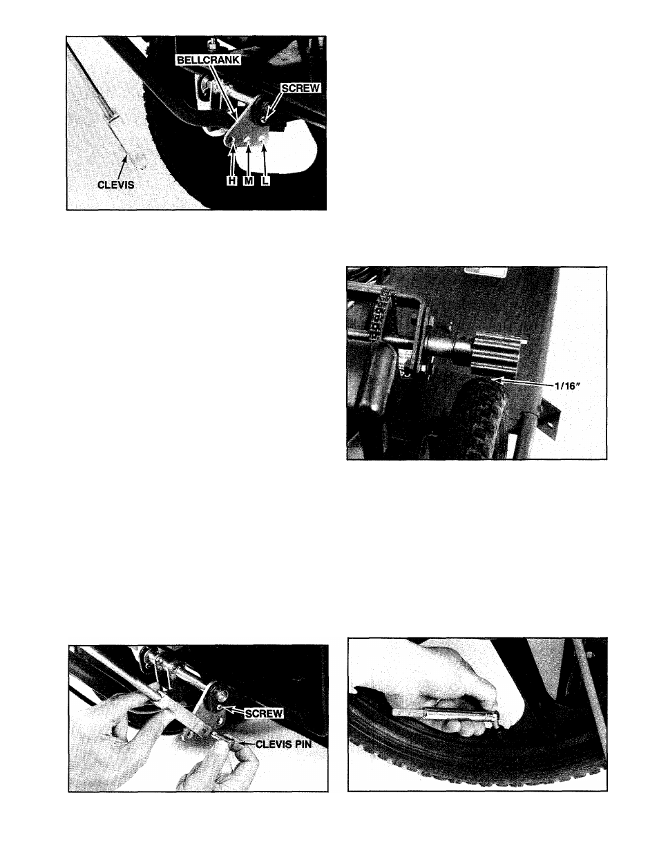
Photo 2-6:
Clevis attaches to bellcrank. Do not remove
alignment screw and nut during attachment steps.
IMPOFnANT
Whenever the handlebar height is changed, the posi
tion of the control rod clevis must be changed accord
ingly. Moving the handlebars changes the tension on the
upper control rod and this tension must be adjusted by
relocating the clevis in the appropriate bellcrank hole.
Refer to the “Handlebar Height Adjustment" instructions
in Section 5 for the correct procedure to follow.
D. Before the mower left the factory, the bellcrank was
rotated upward and secured in place with a #10-24 x
5/8" long Phillips head screw and #10 lockwasher/nut.
See Photo 2-6. This aligns the bellcrank. The bellcrank
must be aligned in this manner every time the control
rod clevis is relocated to a different bellcrank position
ing hole. Do not remove the screw and lockwasher/nut
at this time.
NOTE: If the screw and lockwasher/nut has been
removed, rotate the bellcrank upward and reinstall the
screw and lockwasher/nut.
E. Slide the arms of the clevis over the bellcrank, push
ing the clevis forward as far as it will go.
F. Pull the handle on the wheel drive lever all the way
back into its most reanward position and, while holding
the lever in this position, try to align the clevis hole with
the appropriate bellcrank hole.
Do not let the wheel
drive lever move from its most rearward position while
you are moving the clevis.
G. If the holes line up, insert the clevis pin through the
right side of the clevis and secure it with the spring
clip. See Photo 2-7. If the holes do not line up, remove
the clevis from the bellcrank and adjust the clevis by
rotating it up or down the control rod.
H.
Repeat Steps E, F and G until the holes are
aligned.
I.
Remove the screw and lockwasher/nut (shown in
Photos 2-6 & 2-7) from the bellcrank alignment holes.
You may have to jiggle the bellcrank slightly to free
them. Be sure to save the screw and lockwasher/nut
for any future readjustments of the upper wheel drive
control rod.
J. At this time, check to see that the wheel drive rollers
are not touching the rear tires. See Photo 2-8. With the
wheel drive lever in the upward, NEUTRAL position,
there should be a minimum clearance of 1/16" be
tween the rollers and the tires. This clearance ensures
that the rollers will not drive the wheels when the wheel
drive lever is in NEUTRAL. If there is not at least 1 /16"
of clearance, an adjustment must be made before the
engine is started. Please refer to Section 5, “Adjusting
Wheel Drive Traction” for the necessary adjustment
procedure.
Photo 2-8:
Check for minimum clearance of 1/16"
between rollers and tires. (Belt/pulley safety cover re
moved for photo clarity.)
STEP 4: Check Tire Pressure
A.
Use a pocket-type tire pressure gage to check the
inflation pressures in the rear tires. See Photo 2-9. The
tires should be equally inflated to between 25-30 psi.
B.
Incorrect or unequal air pressure can result in ab
normal tire wear and difficult steering. On self-propelled
models, it can result in poor traction between the wheel
drive rollers and the tires. For best results, check the
inflation pressures after every 10 hours of operation or
once a week, whichever occurs sooner.
Photo 2-7:
Secure clevis with clevis pin and spring clip.
Photo 2-9:
Check tire pressures in rear tires.