Sharpening or replacing the mower blade – Troy-Bilt 1900678 User Manual
Page 26
Attention! The text in this document has been recognized automatically. To view the original document, you can use the "Original mode".
C. Adjust the handlebars to the desired height by
following Steps D and E of the “Attach Handlebars” in
structions on Page 6.
D. Whenever the handiebar height is changed, the
position of the control rod clevis must be changed ac-
cordingiy, reiative to the height position of the handle
bars. To change the clevis to the correct bellcrank hoie,
follow Steps B, C, E, F, G and H of the “Attach Wheel
Drive Control Rod” instructions on Pages 6 and 7.
E. After securing the control rod clevis to the bellcrank
with the clevis pin and spring clip, remove the screw
and nut from the bellcrank alignment holes. Be sure to
save the screw and nut for any future handlebar height
adjustments.
F. With the wheel drive lever in the upright, NEUTRAL
position, check that the clearance between the rollers
and the tires is correct. See “Adjusting Wheel Drive
Traction” on Page 22.
SHARPENING OR REPLACING
THE MOW ER BLADE
Check the condition of the mower blade before each
use. If it is dull or slightly nicked, it should be sharpened
as explained below. A deformed, cracked, or badly nick
ed blade should be replaced with a new one. While
checking the blade, also check that the blade mounting
screw is tightened securely.
cause excessive vibration which could result in engine
damage, or personal injury if the blade should break.
A<
.CAUTION
To avoid porsonni injury, stop the engine, dis
connect the spar< plug wire, keep the wire
away from the spark plug, and allow the engine
and muffler :o coo' before inspecting or servic
ing the blade.
To avoid personal injury from contact with the
sharpened blade, wear heavy gloves or wrap
the blade with ‘.hick rags before working neat it.
To prevent a potential fi''e hazard from possible
gasoline spills, make certain that the area iS
well ventilated and that you keep smokincj
materials, soarks or Fame away.
TOOLS NEEDED: 9/16" Wrench, Flat Metal File.
A. Raise the front of the mower by anchoring the han
dlebars securely or by propping up the mower with stur
dy blocks. On the 8 HP engine only, turn the fuel valve
to the OFF position before tilting the mower back.
B. To remove the blade, hold the blade with one hand
and remove the screw and conical (belleville) washer
using a 9/16" wrench. See Photo 5-8.
C. If the blade needs sharpening, use a file to sharpen
the cutting edge at both ends of the blade. Sharpen
along the original cutting angle, filing in the direction of
the cutting edge only. To maintain proper blade balance,
be sure to remove the same amount of material from
both cutting edges. Check the blade for balance by
balancing it on the round shaft of a pen or pencil. If the
blade cannot be balanced properly, it should be
replaced with a new blade. An unbalanced blade can
Photo 5-8: Remove screw and conical washer.
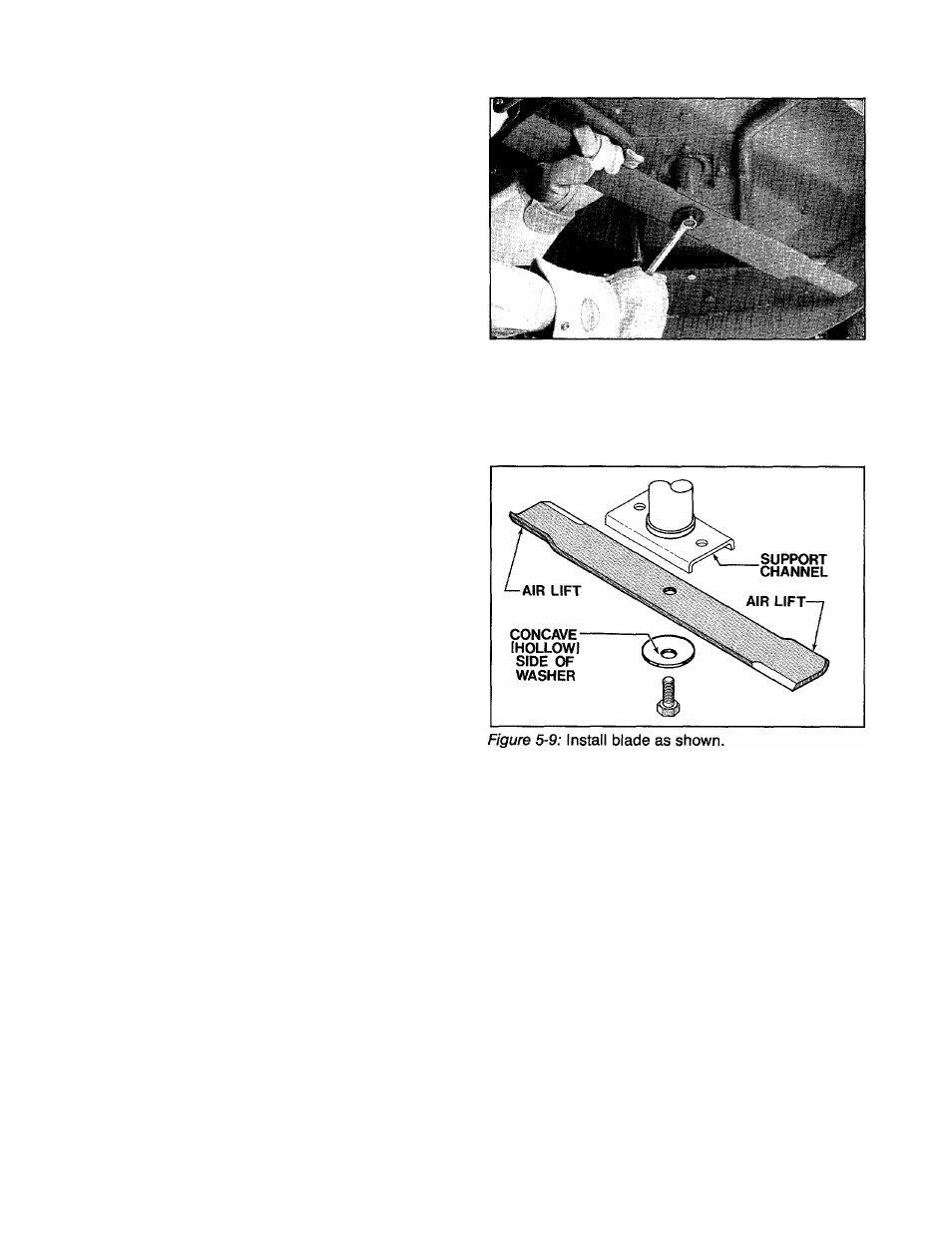
D. To reinstall the blade, first place the conical washer
on the mounting screw, making certain that the con
cave side (hollowed side) of the washer is facing away
from the head of the screw. See Figure 5-9.
IMPORTANT
Do not apply lubricant of any kind to the screw threads.
The screw must be dry in order to work properly.
E. Place the blade in the support channel of the blade
mounting bracket, making certain that the two air lifts
at each end of the blade are pointing upward, toward
the top of the mower deck.
F. Using your fingers only, tighten the screw finger-
tight while gently rocking the blade up and down to
properly seat the blade.
G. Tighten the screw to 38 to 42 ft. lbs. torque. If you
do not have a torque wrench, use the following method
to ensure that the screw is tightened correctly:
1. Using chalk, a grease marker, or paint, draw a
thin line across one-half of the screw head as
shown in Figure 5-10. Draw a similar reference
line on the washer, directly opposite the line on
the screw.
2. Be sure that the screw is tightened finger-tight
as explained in Step F above. Then using the two
lines as reference marks, tighten the screw VA
turns.
24