Replacing the blade drive belt (all models) – Troy-Bilt 1900678 User Manual
Page 30
Attention! The text in this document has been recognized automatically. To view the original document, you can use the "Original mode".
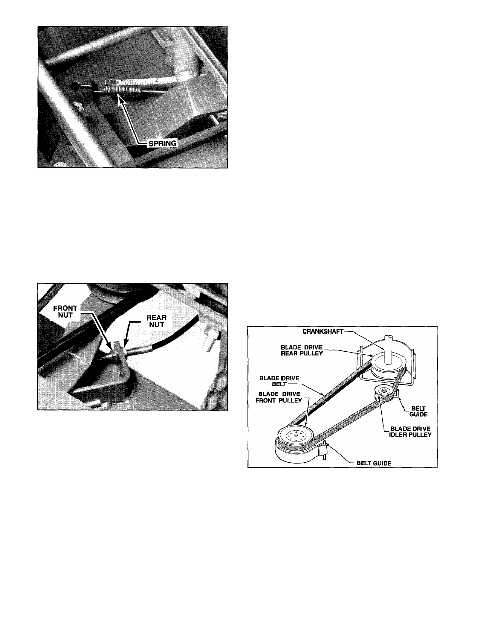
Photo 5-17: Measure length of blade drive tension spring
while blade control is engaged.
E. Belt tension is adjusted by loosening the two jam
nuts on either side of the blade drive cable mounting
bracket and pulling the cable back toward the handle
bars for increased tension, or pushing it forward for
decreased tension. To avoid over-adjusting, it is
recommended that the cable be moved only V
4
" per
adjustment.
F. Using two Va" wrenches, loosen the front and rear
jam nuts that are shown in Photo 5-18.
Photo 5-18: Location of jam nuts on blade drive control
cable (traction drive mounting bracket removed for photo
clarity only).
G. To increase belt tension, unthread the front jam
nut and puli the cable back toward the handlebars.
Thread the front jam nut against the cable bracket,
then thread the rear jam nut against the bracket. Using
two wrenches, hold the rear jam nut and tighten the
front jam nut.
H. To decrease belt tension, unthread the rear jam
nut and push the cable forward. Thread the rear jam
nut against the cable bracket, then thread the front jam
nut against the bracket. Using two wrenches, hold the
front jam nut and tighten the rear jam nut.
I. Check for correct belt tension by measuring the
length of the spring as previously explained in Steps C
and D. Repeat Steps F, G and H as necessary.
J.
Replace the belt/pulley safety cover, fastening it
securely.
IMPORTANT
After adjusting blade drive belt tension, perform the
Blade Brake Control Test Procedure described on Page
34 to ensure that the Blade Brake Control System Is
operating properly. See the WARNING below.
O
WARNING: If the blade does not stop within
3 seconds after releasing the blade control
handle, move the thrott-e control to the STOP posi
tion. Immediately refe*' to the Blade Brake Control
Test Procedure on Page 34. To avoid personal
injury, do not operate the mower until the Blade
Brake Control System is operating properly.
REPLACING THE BLADE DRIVE BELT
(All Models)
n
CAUTION: To avoid personal injury, stop the
engine, disconnect the spark plug wire, keep
the wire av<^ay from the spark plug, and allow the
engine and muffler to cool before replacing the
blade drive belt.
TOOLS NEEDED: 7/16" and two 9/16" Wrenches,
Pliers, Flat Blade Screwdriver.
A.
Remove the belt/pulley safety cover by removing
the three hex nuts and two self-tapping screws.
B. In the following steps, refer to Figure 5-19, which
shows the blade drive belt and pulley system.
Figure 5-19: Blade drive belt/pulley system.
C.
Using two 9/16" wrenches, loosen (but do not
remove) the screw and nut on the blade drive idler
pulley. Then slip the belt up and over the idler pulley
belt guide.
D. Slip the belt down and off the blade drive rear
pulley located on the engine crankshaft.
E.
On self-propelled models only, unhook the upper
end of the wheel drive return spring as shown in Photo
5-20.
F. Remove the belt from the blade drive front pulley
and pull the belt out through the front of the mower.
28