Wheel drive controls (self-propelled models only), Handlebar height adjustment, Height of cut adjustment – Troy-Bilt 1900678 User Manual
Page 18: Engine controls, Engine throttle control, Height of cut adjustment engine throttie control
Attention! The text in this document has been recognized automatically. To view the original document, you can use the "Original mode".
W HEEL DRIVE CONTROLS
(Self-Propelled Models Only)
The wheel drive handle is located below the left side
handlebar grip and the wheel drive lever is located
toward the right side of the handlebars. See Photo 3-1.
These controls are used to engage and disengage
traction drive to the wheels on self-propelled models.
To engage the wheel drive mechanism, first pull the
wheel drive handle up and hold it against the
handlebar grip. Then, push the wheel drive lever all
the way forward until it latches in the fonward position.
See Photo 3-3. This action pulls back the lower wheel
drive control rod which is connected to the wheel fric
tion drive rollers. The rollers then push against the
wheels to propel the mower forward.
The wheel drive handle must be depressed against
the handlebar grip in order to keep the wheels turning.
Releasing the wheel drive handle will disengage the
wheel drive lever, which then disengages the rollers
from the wheels.
For trimming or maneuvering in tight places, you
can disengage the wheel drive (by releasing the wheel
drive handle), and then “creep” the mower forward by
gradually pushing the wheel drive lever forward until
the wheel friction drive rollers contact the wheels. To
stop the fonward motion, simply pull back on the wheel
drive lever.
Photo 3-3: Operation of wheel drive handle and wheel
drive lever.
H
CAUTION: When starting the engine, the
wheel drive lever should be in the upward.
NEUTRAL position. This postion ensures that
the wheels will not starl turning when the engine
starts. To avoid personal injury, do not engage the
wheel orive lever uniti you are reaoy to move the
HANDLEBAR HEIGHT ADJUSTMENT
The handlebars can be adjusted to any of three dif
ferent height settings; LOW, MEDIUM and HIGH.
To change the handlebar height, refer to the “Han
dlebar Height Adjustment” instructions found in Sec
tion 5.
HEIGHT OF CUT ADJUSTMENT
The cutting height can be adjusted to any of four dif
ferent settings: 1-5/8", 2-1/4", 2-7/8", and 3-1/2".
The cutting height has been set at the factory at the
2-7/8" setting. This cutting height is recommended for
initial mowing in rough terrain as it will minimize the
chances of the blade hitting rocks or other hidden
obstructions (see CAUTION statement below).
To change the cutting height to a higher or lower set
ting, refer to the “Height of Cut Adjustment” instruc
tions in Section 5.
B
CAUTION: Before mowing, thoroughly in
spect the area where the mower is to be used
and remove all stones, sticks, wires, bones, nails
and other foreign objects, to prevent personal in
jury caused by throv^n objects.
ENGINE CONTROLS
The following are descriptions of the controls of your
5 HP or 8 HP Briggs & Stratton Engine. Additional in
formation on the safe, efficient operation of your
engine is given in the engine owner’s pamphlet which
was included in your mower literature package. Please
read that pamphlet carefully.
B
CAUTION: To avoid personal injury, do not
attempt to start your engine at this time.
Complete starting instructions for your mowe' are
provided in Section 4. ■ 'Operating Instructions.”
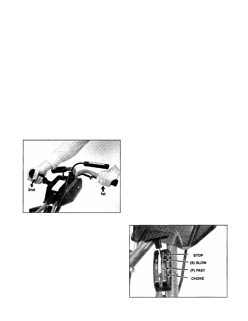
ENGINE THROTTLE CONTROL
On all models, the engine throttle control is located
on the left handlebar. See Photo 3-4. This control
operates a full range of engine speeds. It also activates
the engine choke control when starting the engine,
and stops the engine by grounding out the ignition.
Photo 3-4: Engine throttle control settings.
16