Step 2: install battery mounting bracket, Step 3: connect battery recharging line – Troy-Bilt 1900678 User Manual
Page 13
Attention! The text in this document has been recognized automatically. To view the original document, you can use the "Original mode".
F.
To obtain maximum starting capacity and longest
life, the battery must be fully charged at a rate of 1 to 2
amperes until all cells are gassing freely. (To determine
this, WEAR SAFETY GOGGLES and use a flashlight
to look down into each cell while the battery is being
charged. When gassing freely, the surface of the liquid
electrolyte should be covered with tiny bubbles). The
total charging time should not exceed 12 hours.
®
CAUTION:
Do not charge the battery at a
rate higher than 1 to 2 amperes. Higher
amperages can generate excessive heat and gas
sing, permanently damaging the battery.
G.
When the battery is fully charged, turn off the
charger and then disconnect the cables. Check the
electrolyte levels, and if necessary add distilled or
demineralized water until it just reaches the UPPER
LEVEL LINE.
H.
Replace the filler caps and use a baking soda and
water solution to wash off any electrolyte which may
have spilled on the battery.
IMPORTANT
When the battery will not be used for extended periods
(such as during the winter months), the foiiowing
charging scheduie should be followed:
a. Charge the battery before prolonged storage.
b. Charge the battery after prolonged storage.
Please refer to Section 5 of this manual for battery
maintenance and recharging instrucdons.
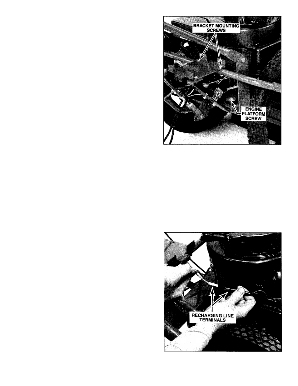
STEP 2: Install Battery Mounting Bracket
A.
Parts Needed: (2) 1 /4"-20 x 1 1 /4" long Hex Hd.
Screws, (2) 1/4"-20" Locknuts, (1) Battery Mounting
Bracket.
B.
The battery mounting bracket must be attached to
the mower’s frame and engine mounting platform at
the three locations shown in Photo 2-17.
C.
Using two 9/16" wrenches, remove the 1 7/8" long
hex hd. screw, 3/8" lockwasher, and 3/8" hex nut from
the right side of the engine mounting platform. See
Photo 2-17. Save this hardware.
D. Align the two holes in the top, front of the mounting
bracket with the two holes in the mower frame cross
piece. Insert the two 1 1 /4" long screws down through
the bracket and frame and loosely attach the two 1 /4"
locknuts.
E.
Align the hole at the bottom of the battery bracket
support leg with the hole in the bottom of the engine
mounting platform (leg goes below platform). Replace
the 1 7/8" long screw, add the lockwasher and nut,
and tighten securely.
F. Now return to the two upper mounting screws and
tighten them securely using two 7/16" wrenches.
Photo 2-17:
Install battery mounting bracket.
STEP 3: Connect Battery Recharging Line
A.
Parts Needed: (1) Plastic tie.
B.
The battery recharging line is a thin red wire, approx
imately 12" long. One end is already connected to the
upper stud on the solenoid (the solenoid is a black,
can-like device that is mounted on the battery bracket
support leg). On the unattached end of the line there is
a white plastic bayonet terminal.
C.
Bring the recharging line over to the right side of
the engine and plug the white terminal into the red term
inal that is attached to the engine with black wires. Push
the terminals firmly together. See Photo 2-18 or 2-19.
Photo 2-18:
Connect recharging line on 22" (5HP
engine) mower.
11