Clean the mower housing and discharge chute, Check tire pressure, Check bolts, screws and nuts – Troy-Bilt 1900678 User Manual
Page 27: Lubrication
Attention! The text in this document has been recognized automatically. To view the original document, you can use the "Original mode".
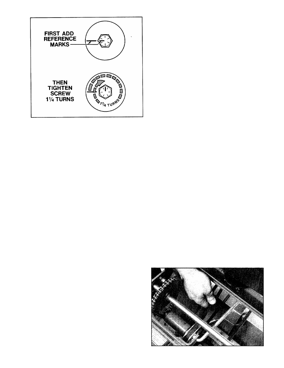
Figure 5-10: If you do not have a torque wrench, tighten
mounting screw as shown above.
H. Remove any rags you may have used to cover the
blade and then lower the front of the mower to the
ground.
I. Reconnect the spark plug wire (and open the fuel
valve on the 8 HP engine) before attempting to start
the engine.
NOTE: Use only a “GRADE 8” screw to mount the
blade. Refer to your Parts Catalog if a replacement
screw is needed.
CLEAN THE MOW ER HOUSING AND
DISCHARGE CHUTE
Clean the underside of the mower housing and the
discharge chute after every mowing. More frequent
cleaning may be necessary under heavy cutting con
ditions.
B
CAUTION: To avoid personal injury, stop the
engine, disconnect the spark plug wire, keep
the wire away from the spark plug, and allow the
engine and muffler to cool before cleaning the
mower housing or discharge chute.
A. Raise the front of the mower about 6" by propping
up the mower deck with sturdy blocks.
B. Spray the underside of the housing and the dis
charge chute with a garden hose to remove clippings
and dirt (avoid spraying the engine or any electrical
connections).
CHECK TIRE PRESSURE
Use a pocket-type tire pressure gage to check the in
flation pressures in the rear tires. The tires should be
equally Inflated to between 25-30 psi. Check the infla
tion pressures after every 10 hours of operation or once
a week, whichever occurs sooner.
CHECK BOLTS, SCREW S AND NUTS
Before each use, check all bolts, screws and nuts for
tightness and keep them tightened securely at all times.
LUBRICATION
Clean and add several drops of light oil to the follow
ing points after every 10 operating hours:
1. All linkages and pivot points.
2. Drive chain on self-propelled models.
3. Both ends of the throttle control cable.
4. Wheel mounting bolts and studs.
5. The spring-loaded dowel pin found on the inside
edge of the two friction drive rollers (see Ref. Nos. 100
and 98 in your Parts Catalog for the location of these
two parts). After oiling, rotate the friction drive roilers to
help spread the oil on the pins.
W HEEL DRIVE BELT TENSION
(Self-Propelled Models Only)
Check the wheel drive belt tension after each 10
hours of operation. Due to normal stretch and wear on
the belt, periodic adjustments may be required. While
checking the tension, also look for obvious signs of
wear such as cracks, cuts or fraying. If the belt is in
poor condition, order a replacement from the Garden
Way Parts Department. This is a special belt made for
your mower and is not available locally.
B
CAUTION: Stop the engine, disconnect the
spark plug wire, and allovi^ the engine and
muffler to cool before inspecting or servicing the
drive belt.
TOOLS NEEDED: 7/16" and
1
/
2
" Wrenches, Flat Blade
Screwdriver, Rubber Mallet.
A.
Remove the belt/pulley safety cover by removing
the three hex nuts and two self-tapping screws.
B. To check for correct tension, use your thumb to
press down in the center of the belt as shown in Photo
5-11. The tension is correct if the belt deflects between
V
2
" to 5/8", under moderate thumb pressure (6-8 lbs.
with V
2
" deflection).
Photo 5-11:
Check wheel drive belt tension.
25