Assembly – Sears 113.206931 User Manual
Page 8
Attention! The text in this document has been recognized automatically. To view the original document, you can use the "Original mode".
assembly
M0UMT1NG JOINTER-PLANER
1. From amontj the loose, parts, find the following
hardware;
.
.
4 Carriage Bolt, 5716-18 X 3/4
■ :
..
3 Hex Head Screws, 5/16-18 x 2
. .
:
7 Lockvi/ashsts, S/16 in. External Type
7 Washers, 11/32 ID
7 Hex Jam Nuts,5/16-1S
^
■
2 Cord Clips- --
■ ^
; ■■■ ■
2. Loosen FENCE LOCK K.NOB, Tilt fence upward and slide
-it toward the pulley..
.
.
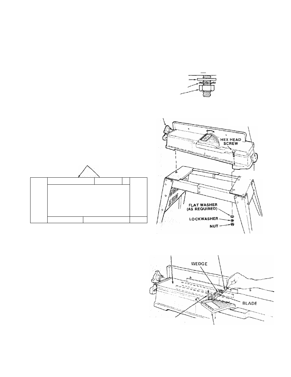
3. Position machino on Leg Set and align moiinfing holes
in machine with holes in Leg Set fetter coded "A".
Mount with three ¡3) 5/16-18 x 2" Long Hex Head
Screws. ' ''
'
.
.
.
.
.
.
.
,
.
4. Place a fiat washer, a lock washer and a nut on each
screw irom underneath the stand and tighten. 7
5. Place handwheel on shaft aligning flat surfaces on shaft
with flat surfaces on handwheel . attach with 1 -1/4
■ in. screw. ;■// ' V ; '
'
,'r ■
1/4-20
TRUSS
HEAD SCREW
SIDE STIFFENER
o
.. ■ 6
; 0
' ■ o ■ .
O
ti/Z/o'V'/ ^
iq 0
.□ ú f ' q
-;o
o
■o
. 0
o
■ o
o
1
1
A-m
B B A
L_/^ END STIFFENER-—
■ ■■ '. . ^ Av
CD
0., ;.;CD
0 1^1
MOTOR SUPPORT AT THIS END
u
-JOfNTER/PLANER
HEX HEAD SCREW
•W
FLAT WASHER
LOCKWASHER
HEX NUT
FENCE LOCK
KNOB
STIFFENER
1-1/4 IN. SCREW
DEPTH OF CUT
HANDWHEEL
CHECKitSlG CUTTER BLADES AND SCREWS
TOOLS NEEDED
5/32"
and
1/8"
Setscrew
Wrenches
ifurnished
with
Jointer). .
Lead Pencil .
Short straight edge (or head of combination square)
1. Insert pencil in space at end of cutterhead to hold
; cutterhead guard open.
.
. . _
2. Lower the infeed table with the Depth of Cut
Handwheel.
_ ^
3. Rest the straight edge on edge on the surface of outfeed
table so it extends across the opening between the
tables, at three positions: near each end and at the
middle of the cutter blade.
4. Rotate the cutterhead by .grasping-the 2" dia, driven
puliey and. makfi sure each knife nicks (touches) the
'straight edge, at .ail three positions. If not, follow
ptocedurc
under
"REPLACING CUTTER BLADES” on
.ppg. -21 and. 22,. .
. ■
, ,
. •: . -.. -
.
GUTFEED TABLE
5/32 IN. SETSCREW
WRENCH
PENCIL
CUTTER GUARD
5. If aicutter, blade adjustment is not required, check each
locking screw, of each wedge (5/32” setscrew wrench)
and tighten if; necessary. Hold the pulley white
tightening screws and be careful that your fingers do not
slip off the wrench."