Carrier 38AN User Manual
Page 22
Attention! The text in this document has been recognized automatically. To view the original document, you can use the "Original mode".
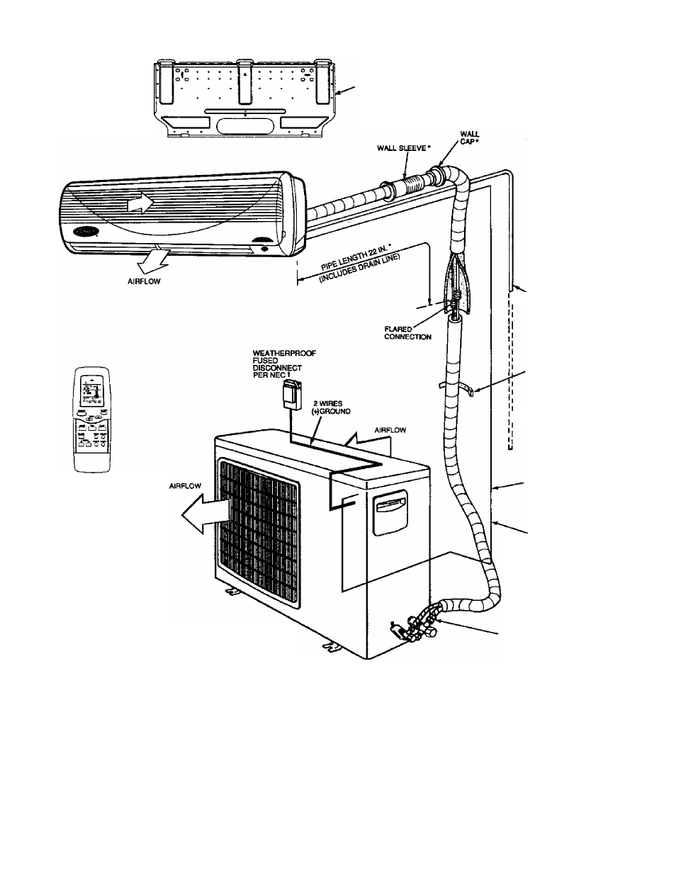
'WALL MOUNTING
BRACKET*
I
'DRAIN LINE*
I TO OPEN DRAIN
(DO NOT TRAP)
WALLSTRAPSt
^ DRAIN
~ HOSE
WIRELESS
CONTROLLER*
EXTENSION t
POWER AND HIGH-
VOLTAGE CONTROL
TO INDOOR UNIT
3 WIRES
(4)GR0UND
LEGEND
NEC — National Electrical Code
'Standard.
tField supplied.
NOTES:
1. All piping must follow standard refrigerant techniques. Refer to
Carrier System Design Manual for details.
2. Do not install a filter drier in mixed phase liquid line.
3. All wiring must comply with applicable local and national codes.
4. Capillary tube expansion device (cooling-only systems only) is lo
cated in №e outdoor unit. Both re№gerant lines must be insulated.
5. Wiring and piping shown are general points-of-connectbn guides only
and are not intended to include all details for a specific installation.
6. Insulate condensate line drain if installed in a conditioned space.
FLARE
CONNECTIONS
TO SERVICE VALVES
Fig. 21 — Typical High Wall System Piping and Wiring
22