A. warning – Carrier 48XL User Manual
Page 9
Attention! The text in this document has been recognized automatically. To view the original document, you can use the "Original mode".
CABINET
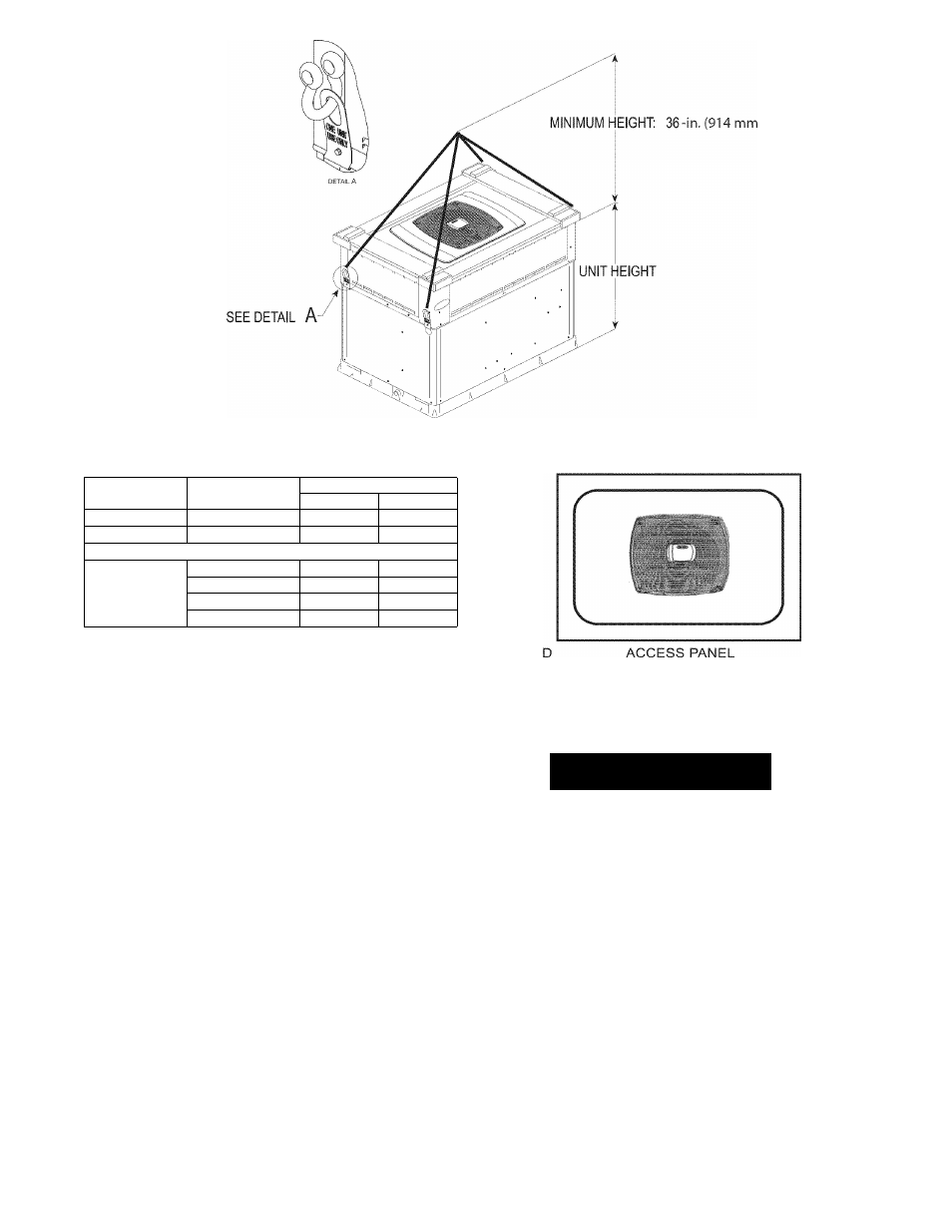
MODEL
RIGGING WEIGHT
lb
kg
Small
48XL-024
420
191
Small
48XL-030
427
194
Large
48XL-036
515
234
48XL-042
537
244
48XL-048
543
246
48XL-060
594
269
NOTE: See dimensional drawing for corner weight distribution. Corner
weights shown on drawing are based on unit-only weights and do not
include packaging.
Fig. 7 - Suggested Rigging
IMPORTANT:
Use flexible connectors between ductwork and
unit to prevent transmission of vibration. Use suitable gaskets to
ensure weather tight and airtight seal. When electric heat is
installed, use fireproof canvas (or similar heat resistant material)
connector between ductwork and unit discharge connection. If
flexible duct is used, insert a sheet metal sleeve inside duct. Heat
resistant duct connector (or sheet metal sleeve) must extend 24-in.
(610 mm) from electric heater element.
3. Size ductwork for max possible air flow (See Table 1).
4. Seal, insulate, and weatherproof all external ductwork. Seal,
insulate and cover with a vapor barrier all ductwork passing
through conditioned spaces. Follow latest Sheet Metal and
Air
Conditioning
Contractors
National
Association
(SMACNA) and Air Conditioning Contractors Association
(ACCA) minimum installation standards for residential
heating and air conditioning systems.
3. Secure all ducts to building structure. Flash, weatherproof,
and vibration-isolate duct openings in wall or roof
according to good construction practices.
CONVERTING
HORIZONTAL
DISCHARGE
UNITS
TO
DOWNFLOW (VERTICAL) DISCHARGE UNITS
A. WARNING
ELECTRICAL SHOCK HAZARD
Failure to follow this warning could result in personal
injury or death.
Before installing or servicing system, always turn off main
power to system and tag. There may be more than one
disconnect switch. Turn off accessory heater power switch if
applicable.
NOTE: If
unit is not equipped with duct covers, accessory duct
covers are required. See pre-sale literature.
1. Open all electrical disconnects and install lockout tag before
starting any service work.
2. Remove side duct covers to access bottom return and
supply knockouts.
NOTE:
These panels are held in place with tabs similar to an
electrical knockout.
3. Use a screwdriver and hammer to remove the panels in the
bottom of the composite unit base.
4. Ensure the side duct covers are in place to block off the
horizontal air openings (See Fig. 8).