Table 1—physical data (con’t) - unit 48xl, Provide clearances, Important – Carrier 48XL User Manual
Page 7: Rig and place unit
Attention! The text in this document has been recognized automatically. To view the original document, you can use the "Original mode".
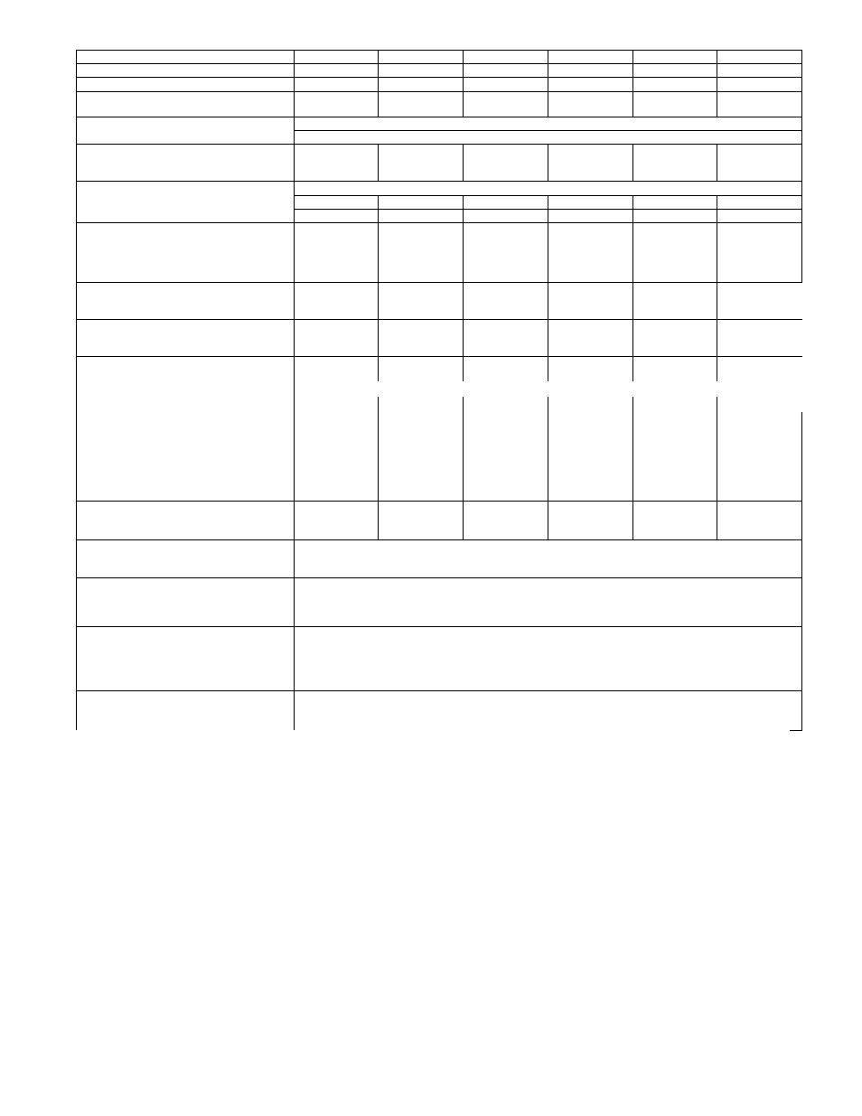
Table 1—Physical Data (Con’t) - Unit 48XL
UNIT SIZE
048090
048115
048130
060090
060115
060130
NOMINAL COOLING CAPACITY (ton)
4
4
4
5
5
5
NOMINAL HEATING CAPACITY (Btu)
90,000
115,000
130,000
90,000
115,000
130,000
OPERATING WEIGHT (lb)
521
521
521
572
572
572
(kg)
236
236
236
259
259
259
COMPRESSORS
2-Stage Scroll
Quantity
1
REFRIGERANT: PURON (R-410A)
Quantity (lb)
15.3
15.3
15.3
15.8
15.8
15.8
(kg)
6.9
6.9
6.9
7.2
7.2
7.2
REFRIGERANT METERING DEVICE
TXV
Size
4 Ton
4 Ton
4 Ton
5 Ton
5 Ton
5 Ton
Part Number
EA36YD149
EA36YD149
EA36YD149
EA36YD159
EA36YD159
EA36YD159
OUTDOOR FAN
Nominal Cfm
3300
3300
3300
3300
3300
3300
Diameter (in.)
22
22
22
22
22
22
(mm)
559
559
559
559
559
559
Motor Hp (Rpm)
1/4 (1100)
1/4 (1100)
1/4 (1100)
1/3 (1110)
1/3 (1110)
1/3 (1110)
OUTDOOR COIL
Rows...Fins/in.
2...21
2...21
2...21
2...21
2...21
2...21
Face Area (sq ft)
19.4
19.4
19.4
23.3
23.3
23.3
INDOOR COIL
Rows...Fins/in.
3...17
3...17
3...17
4...17
4...17
4...17
Face Area (sq ft)
5.7
5.7
5.7
5.7
5.7
5.7
INDOOR FAN
Nominal Airflow (Cfm)
Comfort
Variable based on Comfort Roll back (see User Interface instructions for more information).
Efficiency
1400
1400
1400
1750
1750
1750
Max
1600
1600
1600
2000
2000
2000
Furnace (gas ht.) airflow-Low Stage
815
1215
1255
845
1215
1255
Furnace (gas ht.) airflow-High Stage
1385
1885
1875
1300
1910
1920
Size (in.)
11x10
11x10
11x10
11x10
11x10
11x10
(mm)
279x254
279x254
279x254
279x254
279x254
279x254
Motor HP (RPM)
3/4
3/4
3/4
1
1
1
FURNACE SECTION*
Burner Orifice No. (Qty...Driii Size)
Natural Gas
3...3S
3...33
3...31
3...38
3...33
3...31
HIGH-PRESSURE SWITCH (psig)
Cut-out
670 ± 10
Reset (Auto)
470 ±25
HIGH-PRESSURE SWITCH 2 (psig)
(Compressor Solenoid)
Cut-out
565 ± 15
Reset (Auto)
455 ± 15
LOSS-OF-CHARGE /
LOW-PRESSURE SWITCH
(Liquid Line) (psig)
Cut-out
23 ±5
Reset (auto)
55 ±5
RETURN-AIR FILTERS Throwaway
(in.)t
24x36x1
(mm)
610x914x25
*Based on altitude of 0 to 2000 ft (0 to 610 m).
tRecommended filter sizes for field-installed air filter grilles mounted on the wall or ceiling of the conditioned structure. Required filter sizes shown are based on
the larger of the ARI (Air Conditioning and Refrigeration Institute) rated cooling airflow or the heating airflow velocity of 300 ft/minute for throwaway type or 450
ft/minute for high-capacity type. Air filter pressure drop for non-standard filters must not exceed 0.08 IN. W.C.
Provide Clearances
The required minimum service clearances are shown in 3 and 6.
Adequate ventilation and outdoor air must be provided. The
outdoor fan draws air through the outdoor coil and discharges it
through the top fan grille. Be sure that the fan discharge does not
recirculate to the outdoor coil. Do not locate the unit in either a
corner or under an overhead obstruction. The minimum clearance
under a partial overhang (such as a normal house overhang) is 48
in, above the unit top. The maximum horizontal extension of a
partial overhang must not exceed 48 in, (12f9 mm).
IMPORTANT:
Do not restrict outdoor airflow. An air restriction
at either the outdoor-air inlet or the fan discharge may be
detrimental to compressor life.
Do not place the unit where water, ice, or snow from an overhang
or roof will damage or flood the unit. Do not install the unit on
carpeting or other combustible materials. Slab-mounted units
should be at least 4 in, (102 mm) above the highest expected water
and runoff levels. Do not use unit if it has been under water.
Rig and Place Unit
Rigging and handling of this equipment can be hazardous for
many reasons due to the installation location (roofs, elevated
structures, etc.).
Only trained, qualified crane operators and ground support staff
should handle and install this equipment.
When working with this equipment, observe precautions in the
literature, on tags, stickers, and labels attached to the equipment,
and any other safety precautions that might apply.
Training for operators of the lifting equipment should include, but
not be limited to, the following:
1, Application of the lifter to the load, and adjustment of the
lifts to adapt to various sizes or kinds of loads.
2, Instruction in any special operation or precaution,
3, Condition of the load as it relates to operation of the lifting
kit, such as balance, temperature, etc.
Follow all applicable safety codes. Wear safety shoes and work
gloves,
7