Final checks, Care and maintenance – Carrier 48XL User Manual
Page 32
Attention! The text in this document has been recognized automatically. To view the original document, you can use the "Original mode".
A91431
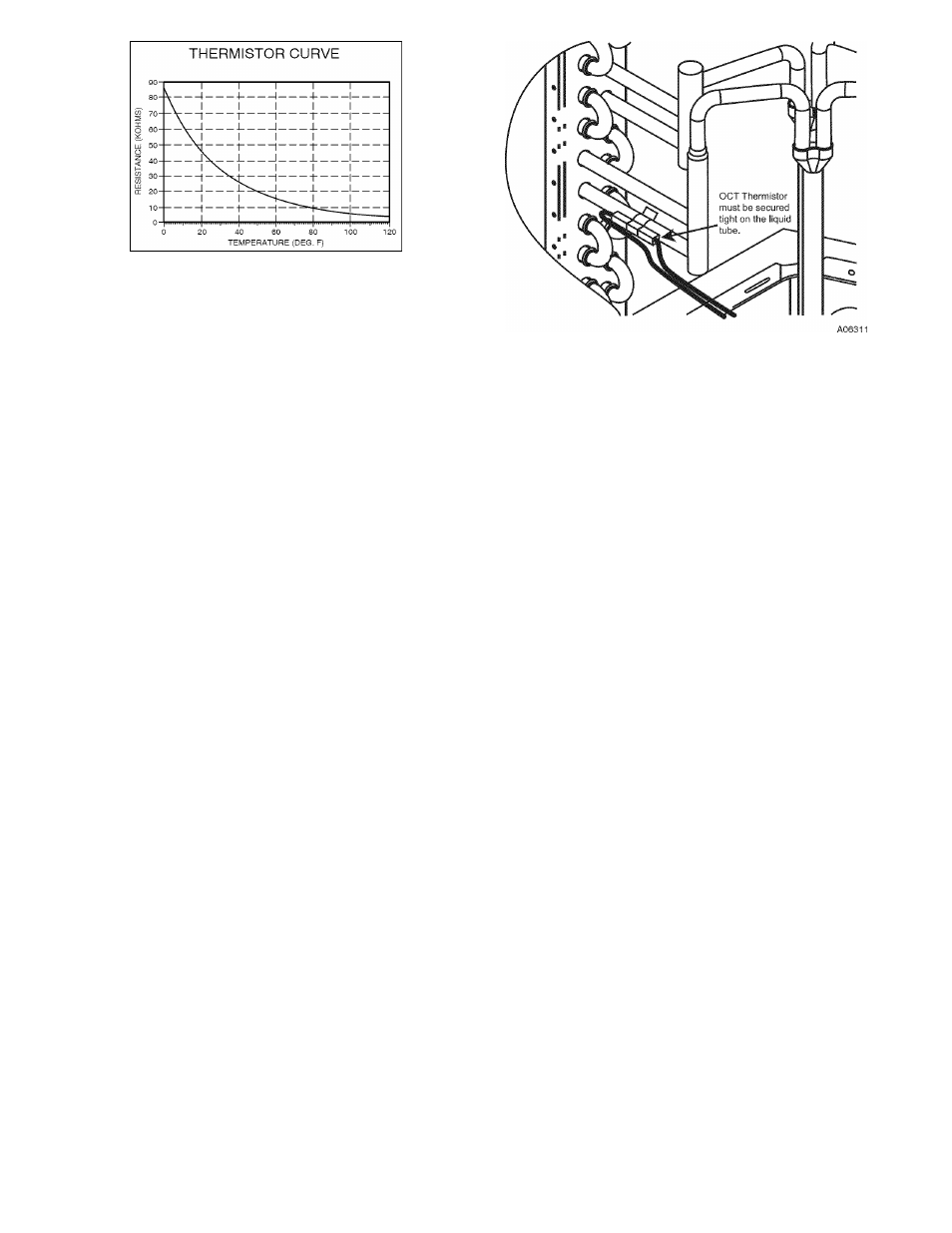
Fig. 25 - Resistance Values Versus Temperature
THERMISTOR SENSOR COMPARISON
The control continuously monitors and compares the outdoor air
temperature sensor and outdoor coil temperature sensor to ensure
proper operating conditions. The comparison is:
• In cooling mode, if the outdoor air sensor indicates > 10 °F
(-12°C) warmer than the coil sensor (or) the outdoor air sensor
indicates > 20°F cooler than the coil sensor, the sensors are out of
range.
• In heating if the outdoor air sensor indicates > 33°F (2°C)
warmer than the coil sensor (or) the outdoor air sensor indicates
> 10°F (-12°C) cooler than the coil sensor, the sensors are out
of range.
If the sensors are out of range, the control will flash the appropriate
fault code as shown in Table 3.
The thermistor comparison is not performed during low ambient
cooling operation.
FAILED THERMISTOR DEFAULT OPERATION
Factory defaults have been provided in the event of failure of
outdoor air thermistor and/or coil thermistor.
If the OAT sensor should fail, low ambient cooling will not be
allowed and the one-minute outdoor fan off delay will not occur.
Defrost will be initiated based on coil temperature and time.
If the OCT sensor should fail, low ambient cooling will not be
allowed. Defrost will occur at each time interval during heating
operation, but will terminate after 3 minutes.
If there is a thermistor out of range error, defrost will occur at each
time interval during heating operation, but will terminate after 3
minutes.
Refer to the Troubleshooting Chart (Table 10) for additional
troubleshooting information.
Fig. 26 - Outdoor Coil Thermistor (OCT) Attachment
FINAL CHECKS
IMPORTANT:
Before leaving job, be sure to do the following:
1. Ensure that all wiring is routed away from tubing and sheet
metal edges to prevent rub-through or wire pinching.
2. Ensure that all wiring and tubing is secure in unit before
adding panels and covers. Securely fasten all panels and
covers.
3. Tighten service valve stem caps to 1/2-turn past finger
tight.
4. Leave Users Manual with owner. Explain system operation
and periodic maintenance requirements outlined in manual.
3. Fill out Start-Up Checklist located at the back of this
manual and place in customer file.
CARE AND MAINTENANCE
For continuing high performance and to minimize possible
equipment failure, periodic maintenance must be performed on this
equipment.
Frequency of maintenance may vary depending upon geographic
areas, such as coastal applications. See Users Manual for
information.
32