Fig. 23 - cooling charging table-subcooling – Carrier 48XL User Manual
Page 27
Attention! The text in this document has been recognized automatically. To view the original document, you can use the "Original mode".
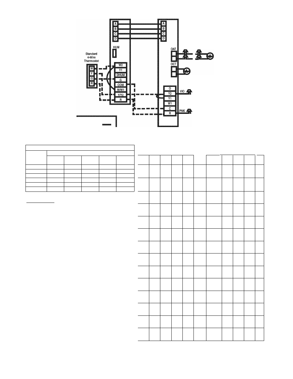
Infinity Furnace
Board
Infinity HP/AC
Board
Outdoor Air Thermistor
(Supplied with lU)
FIELD CONNECTION
REQUIRED
(BLACK WIRES)
Outdoor Coil Thermistor
FACTORY CONNECTED
FACTORY WIRES PROVIDED
FOR FIELD CONNECTION
OF
UTILITY CURTAILMENT
LEGEND
Jumped Wires i
Field Wiring
Fig. 22 - Noii-Coniniuiiicating Emergency Cooling/Heating Wiring Connections
Required Subcooling
°F (°C)
Model Size
Outdoor Ambient Temperature
75(24)
82 (28)
85(29)
95(35)
105(41)
024
15.5(8.6)
15.6(8.7)
15.7(8.7)
15.8(8.8)
15.9(8.9)
030
16,8 {9.3 )
16.4(9.1 )
16.2(9)
15.6(8.7)
15(8.3)
036
14(7.7)
13.9(7.7)
13.9(7.7)
13.8(7.7)
13.7(7.6)
042
19.2(10.7)
19.1 (10.6)
19.1(10.6)
18.9(10.5)
18.7(10.4)
048
21(11,6)
20,8(11,5)
20,7(11.5)
20.4(11.3)
20.2(11.2)
060
16.2(9)
16.6(9.2)
16.8(9.3)
17.3(9.6)
17.8(9.9)
Required Liquid Line Temperature for a Specific Subcooling (R410A)
Required Subcooling
(°F)
ressure
ipsig)
5
10
15
25
Pressure
(kPa)
3
6
8
14
174
56
51
46
36
1200
13
11
8
2
181
59
54
49
39
1248
15
12
9
4
188
61
56
51
41
1296
16
13
10
5
195
63
58
53
43
1344
17
14
12
6
202
65
60
55
45
1393
18
16
13
7
209
67
62
57
47
1441
20
17
14
9
216
69
64
59
49
1489
21
18
15
10
223
71
66
61
51
1537
22
19
16
11
230
73
68
63
53
1586
23
20
17
12
237
75
70
65
55
1634
24
21
19
13
244
77
72
67
57
1682
25
22
20
14
251
79
74
69
59
1730
26
23
21
15
259
81
76
71
61
1786
27
24
22
16
267
83
78
73
63
1841
28
26
23
17
275
85
80
75
65
1896
29
27
24
18
283
87
82
77
67
1951
31
28
25
19
291
89
84
79
69
2006
32
29
26
20
299
91
86
81
71
2061
33
30
27
22
308
93
88
83
73
2123
34
31
28
23
317
95
90
85
75
2185
35
32
29
24
326
97
92
87
77
2247
36
33
30
25
335
99
94
89
79
2309
37
34
31
26
344
101
96
91
81
2372
38
35
33
27
353
102
97
92
82
2434
39
36
34
28
363
104
99
94
84
2503
40
37
35
29
373
106
101
96
86
2571
41
39
36
30
383
108
103
98
88
2640
42
40
37
31
393
110
105
100
90
2709
43
41
38
32
403
112
107
102
92
2778
44
42
39
33
413
114
109
104
94
2847
45
43
40
34
423
116
111
106
96
2916
46
44
41
35
433
117
112
107
97
2985
47
45
42
36
443
119
114
109
99
3054
48
46
43
37
453
121
116
111
101
3123
49
47
44
38
463
122
117
112
102
3192
50
47
45
39
473
124
119
114
104
3261
51
48
46
40
483
126
121
116
106
3330
52
49
47
41
493
127
122
117
107
3399
53
50
47
42
503
129
124
119
109
3468
54
51
48
43
513
130
125
120
110
3537
55
52
49
44
523
132
127
122
112
3606
56
53
50
44
533
133
128
123
113
3675
56
54
51
45
Required Subcooling (°C)
Charging Procedure
1- Measure Discharge line pressure by attaching a gauge to the service port.
2- Measure the Liquid line temperature by attaching a temperature sensing device to it.
3- Insulate the temperature sensing device so that the Outdoor Ambient doesn’t affect
the reading,
4- Refer to the required Subcooling in the table based on the model size and the
Outdoor Ambient temperature.
5- Interpolate if the Outdoor temperature lies in between the table values. Extrapolate if
the temperature lies beyond the table range.
6- Find the Pressure Value corresponding to the the measured Pressure on the
Compressor Discharge line.
7- Read across from the Pressure reading to obtain the Liquid line temperature for a
required Subcooling.
8- Add Charge if the measured temperature is higher than the liquid line temperature
value in the table.
9- Add Charge using the service connection on the Suction line of the Compressor.
50DU500166-2.0
A08423
Fig. 23 - Cooling Charging Table-Subcooling
27