Unit protection, Pumpdown procedure, Compressor service – Carrier 38SE User Manual
Page 8
Attention! The text in this document has been recognized automatically. To view the original document, you can use the "Original mode".
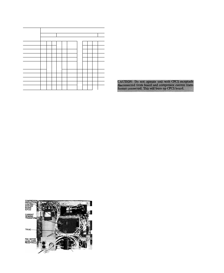
Table 8 — Chargemaster® Charging Chart
(38SE Capillary Tube or AccuRater^'^ Systems)
OUTDOOR
TEMP (F)
EVAPORATOR TEMP (F)
32| 34136
38 40 42 im 46 |48 50 52
54
Suction Line Temperature (F)
60
60
— -
65
4%
58
65
70
41
48
58
68
70
m
75
35
41
48
58
68
—
80
31
36 .42
50
59.
69^
"To”
'
!-------
w.
44
40
w
47
53 j 61
82
■■¿9'78“
—
95
42
48 53
59
67
79
100
43 I 47
52
58
68 88
105
I 44
48
53
60
75
104
no
49
54
65
80
115
--
50
62
69
Example
UNIT PROTECTION
High-Pressure Relief Valve
is located in compressor when so
equipped. Relief valve opens at a pressure differential of
approximately 450 — 550 psi between suction and discharge.
Valve permits pressure equalization at running condition
described above and during unit shutdown. A hissing sound
during pressure equalization does not indicate bad valves.
High Pressurestat
is located on unit liquid line. High
pressurestat settings are; cutout, 425 ± 5 psig; cut-in, 320 ±
20 psig.
Low Pressurestat
is located on unit suction line. Low
pressurestat settings are; cutout, 31 ± 4 psig, cut-in, 60
(+15,-0) psig.
Internal Temperature And/Or Current Sensitive Overloads
reset automatically when internal motor temperatures drop
to a safe level (overload may require up to 30 minutes to
reset). When internal overload is suspected of being open,
check by using an ohmmeter or continuity tester. If
necessary, refer to Carrier Standard Service Techniques
Manual, Chapter 2, for complete instructions.
Outdoor Fan Thermostat
(38SE055 and 38GR units)
switches fan to high speed (Table 5) when outdoor
temperature reaches 90 F — maintains proper condensing
temperature at high outdoor air temperatures. Thermostat
is located on Control Panel, Fig. 7.
Filter-Drier
is installed in liquid line.
FAN THERMOSTAT
«F SO EQUIPPED)
CONTROL
TRANSFORMER
(DUAL SECONDARY)
'CS
CEPTACLE
ITROL RELAY
Compressor Protection Control System
(CPCS — Solid
State, Fig. 7) provides; compressor motor locked rotor
protection; compressor start winding protection; compres
sor motor running overload protection; compressor over
temperature protection; contactor anti-chatter protection.
The CPCS also provides for a 4- to 6-minute delay before
restarting compressor after shutdown for any reason. If
compressor loading was light at the moment compressor
was shut off, the delay will be approximately 4 minutes. If
loading was heavy, the delay will be approximately 6
minutes. The CPCS board is located on control panel
beneath a sheet metal protective cover. To troubleshoot the
CPCS, remove protective sheet metal cover, and use unit
label diagram or wiring booklet with Control Circuit
Troubleshooting Chart, page 9.
TROUBLESHOOTING CHART NOTES (Page 9);
1. Ensure thermostat calls for cooling before troubleshoor-
ing unit.
2. To disconnect plug from receptacle on CPCS board —
press in tabs located on the receptacle and pull plug
gently while holding tabs. Do not pull on wiring.
3. When performing troubleshooting checks, CPCS recep
tacle must be plugged into CPCS board,
4. Receptacle female connections, which do not grip the
male pin tightly, may be repaired with a small pen knife.
5. When taking meter readings at CPCS receptacle, bottom
meter probe into terminal hole to ensure good electrical
contact.
6. Replace CPCS board if electrical short circuit causes
compressor failure. An electrical short in compressor can
short the triac (electronic switch located on CPCS
board). Triac may fail in a closed (conducting) position
and not open the control circuit.
PUMPDOWN PROCEDURE
The 38GR,SE units may be pumped down in order to
make repairs on low side of system without losing complete
refrigerant charge.
1. Attach pressure gage to suction service valve gage port.
2. Frontseat the liquid line valve.
3. Jumper low-pressure switch.
4. Start unit and run until suction pressure reaches 5 psig
(see Caution).
5. Shut unit off and frontseat suction valve.
6. Vent remaining pressure to atmosphere.
CACTfC^' Thtf 58GR
«fill -idd c»nly
suppii&l
af
msv icaus« tiKtts 1« syde op
pre^pf-
stsi
by & djsdtejfgi pfissiiro a
sudifpti rtp? i>i AtOicin"
fessfore stis.'ifoi!
reiscte ? ppit, ff sha «¿rctifa, abKi urti! >4i
fipataeat awtsstsi 'tslve vpiit
fc-
CONTACTOR
Fig. 7 — Control Panel (Cover Removed)
COMPRESSOR SERVICE
Unit Single-Phase Compressors
of the split capacitor (PSC)
type require an equalized system pressure to start. When
supply voltage is within 10% limit and compressor does not
start, give compressor a temporary capacitance boost. See
f
V-