Carrier 38SE User Manual
Page 6
Attention! The text in this document has been recognized automatically. To view the original document, you can use the "Original mode".
necessaiy, refer to Carrier Standard Service Techniques
Manual, Chapter 1, for system evacuation-dehydration
instructions.
When 38GR,SE condensing units are connected to other
than a Carrier evaporator, evacuate system and weigh in
charge shown in Table 5 or use sight glass method of
recharging.
D» iiot
toe sysieiss. A» om-
Weight Method
— Refer to Table 5 or unit nameplate for
correct system refrigerant charge. Blow any refrigerant
remaining in system before recharging.
When system is not evacuated, subtract the following
amount from total charge;
38GR,SE002 - .10 lb (1.6 oz)
38GR,SE003,004,045,005,055,006 - .20 lb (3.2 oz)
Keep refrigerant recharge within one oz of specified
charge on 002 systems and within 2 oz on 003,004,045,
005,055,006 systems.
Dial-a-charge charging cylinder is an accurate device used
to recharge systems by weight. These cylinders are available
at refrigeration supply firms.
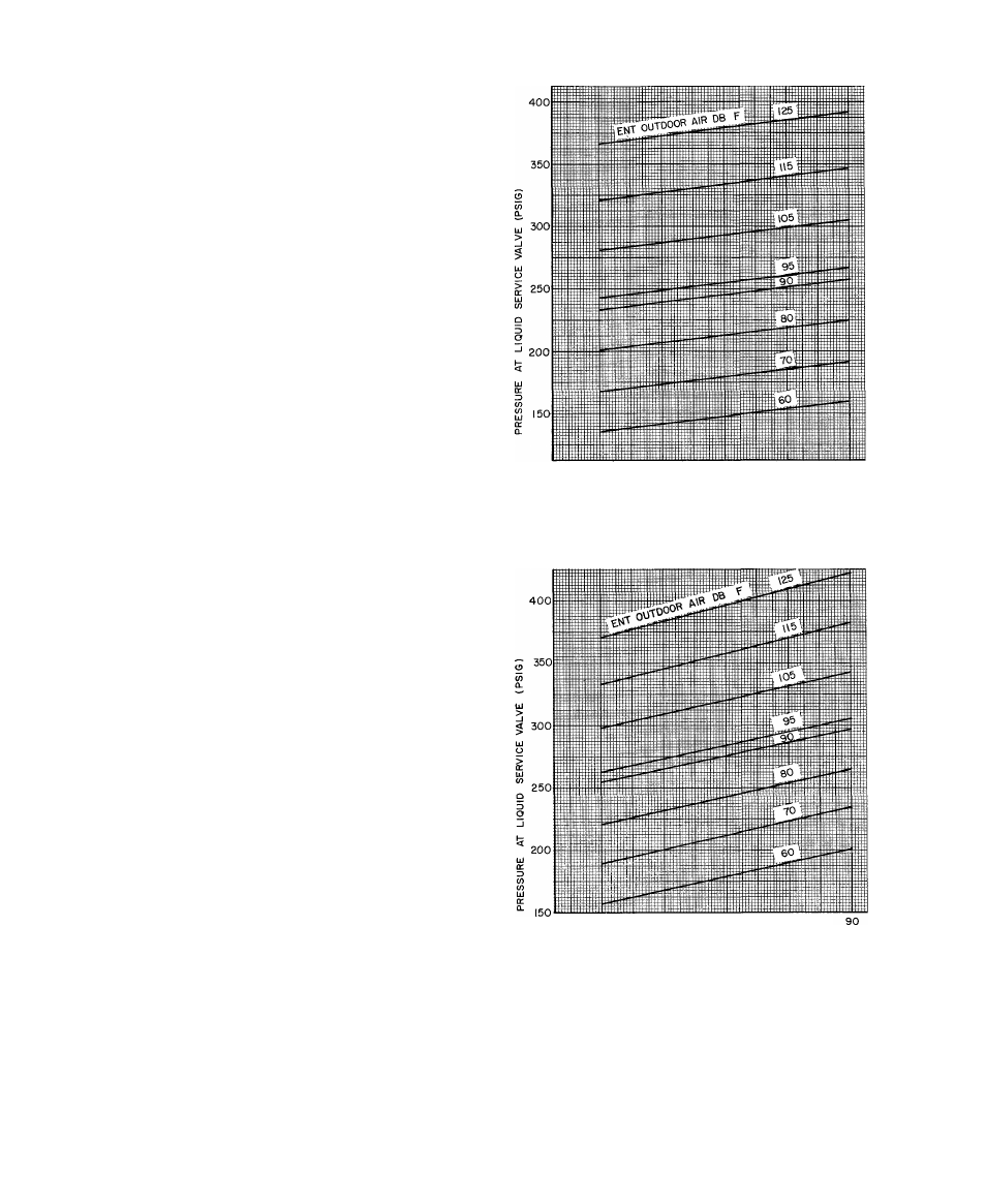
Charging Chart Method
38GR THERMAL EXPANSION VALVE SYSTEMS - Use
Charging Chart, Fig 4 or Fig. 5. See Carrier Standard
Service Techniques Manual, Chapter 1, for procedure.
38SE CAPILLARY TUBE OR
ACCURATERT
m
SYSTEMS
— Use Charging Chart, Fig. 6, and the following procedure;
1. Operate unit a minimum of 10 minutes before checking
charge.
2. Measure suction pressure by attaching a gage to suction
valve service port.
3. Measure suction line temperature by attaching a service
thermometer to unit suction line near compressor.
(Insulate thermometer for accurate readings.)
4. Measure outdoor (condenser inlet) air dry-bulb temper
ature with second thermometer.
5. Refer to Charging Chart (Fig. 6). Find condenser air
temperature and project horizontally to curve showing
suction pressure.
6. From intersect point, project vertically downward to
chart suction line temperature.
7. If unit has a higher suction line temperature than chart,
add refrigerant until chart temperature is reached.
8. If unit has a lower suction line temperature than chart,
bleed refrigerant until chart temperature is reached.
9. If condenser inlet air temperature or unit suction
pressure changes, change to new suction line tem
perature on chart.
Chargemaster® Operation
— Operate unit 10 minutes
before using Chargemaster (Carrier Part No. 38GC680004).
1. Tape Chargemaster feeler bulb to suction line close to
condensing unit. Insulate bulb. Ensure suction line is
clean for good contact with bulb.
2. Connect refrigerant drum to Chargemaster inlet port
with drum in position for vapor charging.
3. Connect Chargemaster outlet port to unit suction valve
service port.
4. Crack valves on refrigerant drum and Chargemaster to
purge lines from drum to suction valve. After purging
lines, close valve on Chargemaster only.
5. Measure outdoor air dry-bulb temperature.
f
50
60
70
80
90
PRESSURE AT SUCTION SERVICE VALVE (PSIG)
Fig. 4 - 38GR002,003,004,045,005 Charging Chart -
TXV Systems
50
60
70
80
PRESSURE AT SUCTION SERVICE VALVE (PSIG)
Fig. 5 — 38GR006 Charging Chart — TXV Systems
6. Crack unit suction valve and read evaporator temper
ature at red needle position on Chargemaster temper
ature gage and suction line temperature at black needle
position.
CAOTICA;
'