Evaporator temp (f) – Carrier 38SE User Manual
Page 7
Attention! The text in this document has been recognized automatically. To view the original document, you can use the "Original mode".
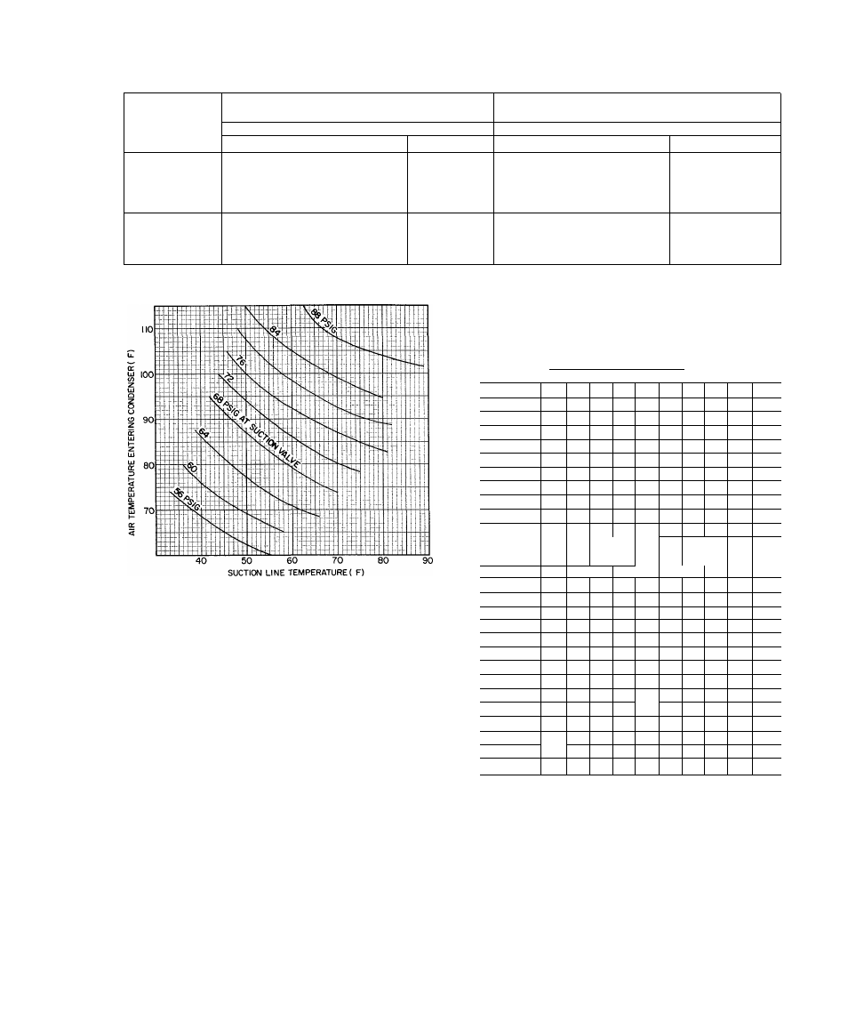
Table 6 — Refrigerant Charging Methods (Carrier Approved Systems)
COND UNIT ;
METHODS OF CHECKING
OR ADJUSTING CHARGE
METHODS FOR
COMPLETE RECHARGING
System Refriqerant Control
System Refrigerant Control
AccuRater^M Capillary Tube
TXV
AccuRater Capíllary Tube
TXV
38GR
Chargemaster®
Charging Chart
er
Sight Glass
Weight Method
Plus
Chargemaster
Weight Method
Plus
Charging Chart
or
Sight Glass
38SE
Chargemaster
or
Charging Chart
Sight Glass
Weight Method
Plus
Chargemaster or
Charging Chart
Weight Method
Plus
Sight Glass
r
NOTE; 38SE operates at lower head pressure than comparable units Do not expect as high pressure when charging or adding charge
Table 7 — Chargemaster Charging Chart
(38GR Capillary Tube or AccuRater Systems)
Fig. 6 — 38SE Charging Chart
(Capillary Tube or AccuRater Systems with or
without Suction-Liquid Line Heat Interchange)
7. Enter Chargemaster Charging Chart, Table 7 or 8, at
outdoor air temperature (step 5) and evaporator temper
ature (step 6). Find the suction line temperature
required for correct system charge. If actual suction line
temperature (step 6) is higher than table value, the
system is undercharged. If suction line temperature is
lower than table value, the system is overcharged.
Example: At outdoor air temperature of 85 F and
evaporator temperature of 44 F, the system will be
correctly charged at 71 F ±2 F suction line temperature.
See Table 8.
8. Add charge by slowly opening Chargemaster valve. If
necessary, reduce charge by bleeding at liquid line
service valve. Check outdoor air and evaporator temper
ature during procedure. If they change, refer back to
Suction Line Temperature table for new value.
Correct use of Chargemaster ensures an optimum refrig
erant charge will be in system when conditions and system
components are normal. However, the Chargemaster does
not solve or fix system abnormalities. It indicates correct
charge for condition of system. It will not make corrections
for dirty filters, slow fans, excessively long or short suction
lines or other abnormal conditions. This charging device
ensures that a correct relationship exists between outdoor
temperature, evaporator temperature, and suction line
temperature on a specific system.
OUTDOOR
TEMP (F)
EVAPORATOR TEMP (F)
21
I
25
I
28
I
31
I
34
I
37
Ml
43
I
45 48
Suction Line Temperotures
60
32
40
51
m
62
30
38
49
64
28
37
47
60
66
27
35
45
57
68
34
43
54
67
70
32
41
52
64
72
31
39
50
61
72"
74
30^
37
48
58
69"
76
29
36
46
56
66
78
27
35
44
54
63..
80
_
26
33
42
52
61 " w-
82
m
39
40
.50
80
76
—
86
29
37
46
55" "63
73
85
88
35
44
53
61
70
81
90
34
42
51
59
68
78
90
92
33
41
49
57
65
75
86
94
39
47
55
63
72
83
96
38
45
53
61
70
80
98
36
44
51
59
67
77
100
42
49
57
65
75
102
41
48
55
63
73
104
39
46
53
61
70
106
45
51
59
68
108
43
49
57
65
110
41
47
55
63
112
46
53
61
114
50
59
Example
*Saturated evaporator temperature which is the equivalent tem
perature of pressure taken at the condensing unitsuction service
valve
Sight Glass Method
— A satisfactory operating charge can
he obtained on thermal expansion valve systems by
charging to a clear sight glass. For optimum charge, elevate
high-side pressure to 380 ±10 psig by blocking condenser
fan discharge or condenser entering air. Charge to a clear
sight glass while holding high-side pressure constant. For
peak efficiency, adjust charge to yield a liquid refrigerant
temperature at the evaporator that is approximately the
same as outdoor dry-bulb temperature.